
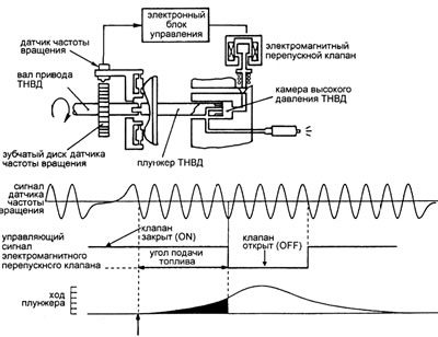
Pic. 3. Fuel Injection Volume Control Method
When the diesel engine is not operating on the regulatory characteristics, mainly when reaching the limiting characteristics, the output signal of the frequency controller is automatically limited to the values calculated in the electronic unit based on the signals received from the intake air temperature, boost pressure and coolant temperature sensors.
When the injection pump shaft rotates, the cams of the washer rigidly connected to the plunger (pic. 3). starting from a certain angle of rotation of the shaft, they run into rollers rotating on axes in a washer that is free relative to the shaft. The cams, starting from the rollers, move the plunger to the right, compressing the fuel in the high pressure chamber of the injection pump. The return stroke of the plunger is carried out due to the springs acting on the cam washer. One of them is shown in fig. 2 below the plunger. The plunger, which rotates together with the shaft, by a channel with a radial outlet made in it, alternately communicates the high-pressure chamber of the high-pressure fuel pump with the high-pressure lines of the nozzles of the corresponding cylinders. The HPFP high-pressure chamber is connected to the drain through a normally open conical valve of an electromagnetic bypass valve controlled by an electronic unit. Speed sensor (position of the injection pump shaft), interacting with a gear disk rotating with a shaft, generates a sequence of rectangular electrical impulses. Each tooth of the disc generates one pulse. There are no teeth in the sectors of the disk corresponding to the angles of the beginning of the preparation of fuel supply to the next engine cylinders. By the time the plunger's working stroke begins, the electromagnetic bypass valve must be closed under the action of an electrical impulse received by it from the electronic control unit. The moment of the beginning of the working stroke of the plunger is detected by the electronic control unit by lengthening the pause between the pulses of the shaft position sensor when the sensor passes through the disk sector without teeth. With the start of the working stroke, the injection pump plunger, moving to the right, creates fuel pressure in the high-pressure chamber, sufficient to open the nozzle connected to this chamber. Fuel injection into the cylinder begins. To stop injection, the electronic control unit turns off the solenoid valve, its shutter opens, communicating the high pressure chamber with a drain into the fuel tank. The pressure in the injection pump chamber and in front of the nozzle drops, the nozzle closes and the injection ends. The amount of cyclic fuel supply is determined by the injection angle, starting from the moment the nozzle opens and ending at the moment the solenoid valve is turned off. Thus, the feed rate is set by changing the duration of the electrical impulse generated by the speed controller in the electronic control unit.
Solenoid relief valve
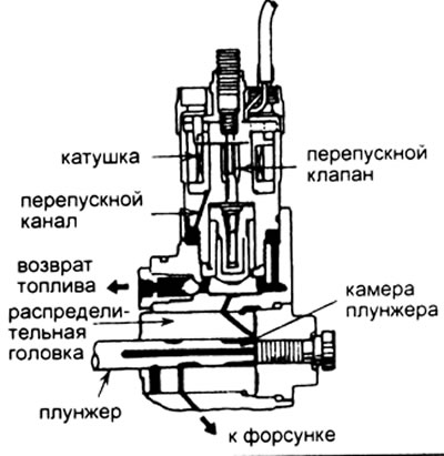
Pic. 4Solenoid bypass valve device (cross section)
The electromagnetic bypass valve is used to control the amount of fuel supply by opening and closing the fuel return line from the high pressure chamber of the injection pump to the fuel tank in accordance with signals from the electronic control unit. The amount of injected fuel is controlled by increasing or decreasing the period between the start of the plunger lift and the opening of the fuel return channel. The solenoid bypass control valve is a dispenser of fuel supplied to the cylinders. The device of the electromagnetic bypass valve is shown in Figure 4. The operation of the electromagnetic bypass valve is illustrated by a diagram of the change in voltage supplied by the electronic control unit to the solenoid coil (see fig. 5). For faster response (shutter closing) valve, a boost voltage of the order of 50 V is briefly applied to the coil, obviously exceeding the long-term allowable voltage under the coil heating conditions. After the valve is activated, the voltage on the coil decreases to 0.5 V. Due to the decrease in magnetic resistance in the activated electromagnet, this voltage is sufficient to hold the electromagnet armature attracted together with the valve. As a result, the consumption of electrical energy and the heating of the electromagnet are radically reduced. In addition, conditions are created to accelerate the shutdown (shutter opening) valve. After the valve is turned off, voltage pulses are supplied to its coil from the electronic unit (on a triangular diagram), the amplitude of which is obviously not sufficient to trigger the valve. These pulses can be used, for example, to diagnose a metering valve. The solenoid bypass valve is mounted vertically on the distributor head at the rear top of the injection pump housing.
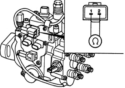
When enabled "ignition" between terminals 1 and "Earth" battery voltage is applied. This makes it possible to turn on the solenoid metering valve on a running diesel engine. On shutdown "ignition" the voltage is removed from the dispenser coil and it acts as a shut-off valve. Diesel stalls. In case of fuzzy operation of the plunger (mechanical wear, fuzzy and incomplete opening of the key transistor, bad contacts in the connector) the amount of injected fuel decreases, the engine power drops, its start-up, both cold and hot, is difficult.
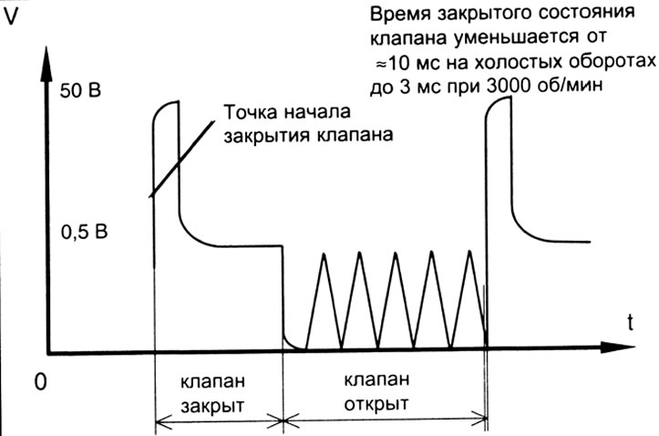
Pic. 5 Diagram of the change in voltage supplied to the coil of the electromagnetic bypass valve
Checking the resistance of the electromagnetic bypass valve
1. Turn off "ignition".
2. Disconnect the solenoid bypass valve connector.
3. Measure the resistance between the valve terminals. The resistance value should be in the range of 1.0 - 2.0 ohms at 20°C.
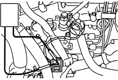
Pic. 6 Checking the resistance of the electromagnetic bypass valve
Checking the supply voltage
1. Turn off "ignition".
2. Disconnect the solenoid bypass valve connector.
3. Turn on "ignition".
4. Measure the voltage between "earth" and connector terminals. The voltage must be: at the power terminal (black wire) 13 V, at the terminal of the key transistor for controlling the operation of the valve (red wire) 10.5 V.
5. If the voltage is out of specification, check the wiring and relay.
Note: There are several modifications of the electronically controlled injection pump, and the valves on them have different threads.
Pic. 7Checking the voltage of the solenoid bypass valve