
Disassembly
1. Remove the distributor cap without removing the high voltage wires.
2. Remove the distributor rotor.
3. Remove the protective cover (dust deflector) ignition coils.
4. Remove the protective cover (dust deflector) switch.
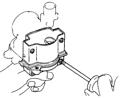
5. Remove the ignition coil.
A) Remove the two nuts and disconnect the four wires from the ignition coil leads.
b) Loosen the four screws and remove the ignition coil and gasket.
6. Remove the switch.
A) Loosen the three screws and disconnect the three wires from the switch leads.
b) Loosen the two screws and remove the switch.
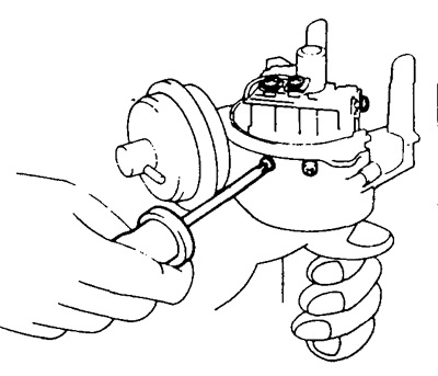
7. Remove the vacuum ignition timing regulator.
A) Loosen the two screws and disconnect the connecting wire terminal.
b) Disconnect the governor drive linkage from the ignition timing sensor base plate ("chopper plates") and remove the vacuum ignition timing adjuster.
8. Remove the connecting wire of the distributor.
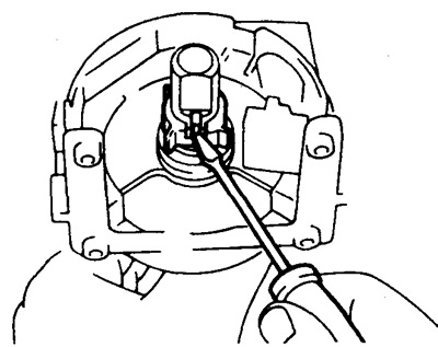
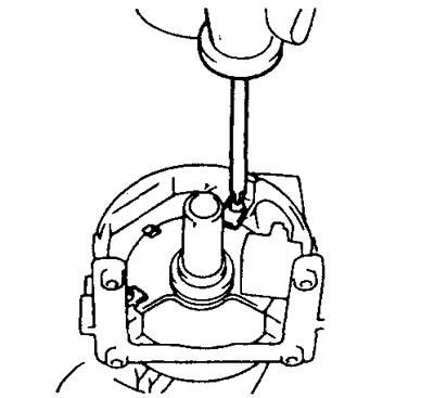
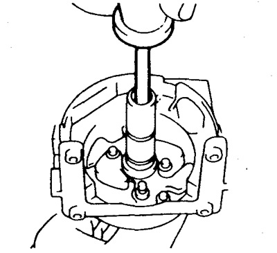
9. Remove a rotor of the gauge of the moment of ignition.
Use a small screwdriver to pry out the rotor set spring.
Then remove the ignition timing sensor rotor.
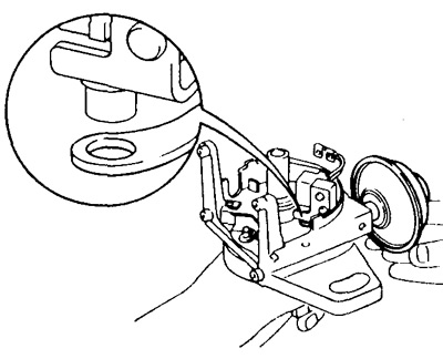
10. Remove the ignition timing sensor base plate ("breaker plate") and the induction coil of the sensor.
Loosen the two screws and remove the two clamp washers. Remove the base plate of the ignition timing sensor with induction coil.
11. Remove the centrifugal ignition timing adjuster springs.
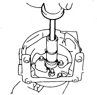
12. Remove the ignition timing sensor rotor drive shaft.
A) Remove the seal plug.
b) Remove the screw from the end of the centrifugal governor drive shaft.
V) Remove the ignition timing sensor rotor drive shaft.
13. Remove the weights of the centrifugal regulator by first removing the split lock washers with a small screwdriver.
Examination
(See section "Checking distributors after disassembly").
Assembly
1. Install centrifugal governor weights and secure with split washers.
2. Apply a light coat of grease to the centrifugal drive shaft.
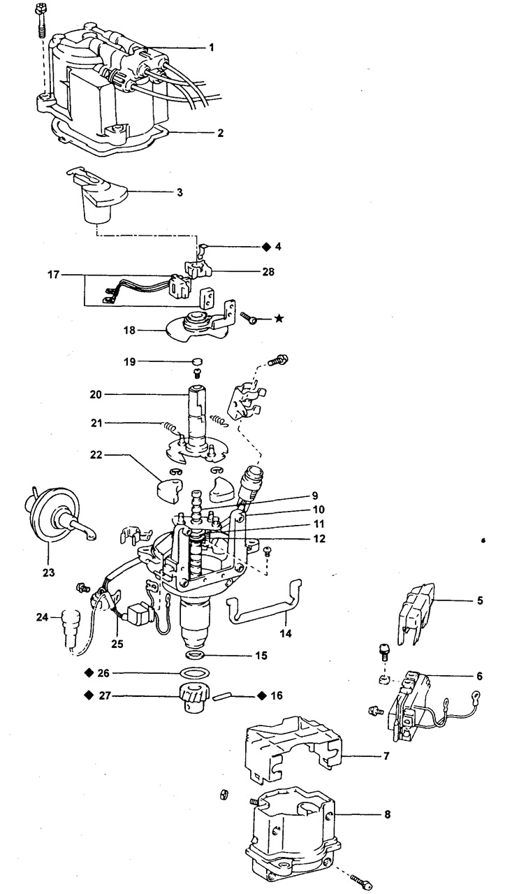
Distributor (non-contact ignition system without electronic ignition timing control).
1 - distributor cap, (with high voltage wires),
2 - gasket,
3 - distributor rotor,
4 - setting spring,
5 - protective cover (dust deflector) switch,
6 - switch,
7 - protective cover (dust deflector) ignition coils,
8 - ignition coil,
9 - distributor drive shaft,
10 - distributor housing,
11 - flat washer,
12 - thrust washer,
14 - gasket,
15 - flat washer,
16 - connecting pin,
17 - induction ignition timing sensor,
18 - base plate of the ignition moment sensor ("breaker plate"),
19 - gland plug,
20 - rotor shaft of the ignition moment sensor,
21 - spring of the centrifugal ignition timing regulator,
22 - weight of the centrifugal ignition timing regulator,
23 - vacuum ignition timing controller,
24 - diagnostic connector,
25 - distributor connecting wire,
26 - sealing ring,
27 - distributor drive gear,
28 - ignition timing sensor rotor,
♦ - parts not subject to reuse,
* - parts covered with insulating material.
3. Install the ignition timing sensor rotor drive shaft.
A) Install the ignition timing sensor rotor drive shaft onto the centrifugal governor drive shaft as shown.
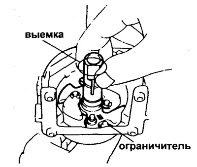
b) Screw the screw into the end of the rotor drive shaft of the ignition timing sensor.
V) Apply a layer of grease to the recess of the ignition timing sensor rotor drive shaft and install the plug in its end.
4. Establish springs of a centrifugal regulator of an advancing angle of ignition.
5. Install base plate ("breaker plate") and an ignition timing sensor induction coil.
A) Align the notches of the base plate and the breaker body, and install the base plate and induction coil.
b) Secure the base plate with two flat washers with screws.
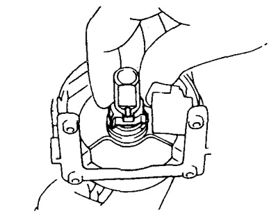
6. Establish a rotor of the gauge of the moment of ignition.
Align the slots and slide the sensor rotor with the new spring onto the drive shaft.
7. Check the air gap (see page 62).
- Gap size: 0.2 - 0.4 mm.
8. If necessary, replace the base plate and ignition timing sensor induction coil.
A) Remove the rotor, base plate and ignition timing sensor induction coil (see above).
b) Use kerosene or petrol to clean the threaded holes and screw threads.
V) Install new base plate ("breaker plate").
G) Lubricate the thread ends with anaerobic glue for a length of 3-5 mm.
d) socket wrench (hexagon) fasten the new sensor induction coil with screws in such a way as to ensure the required air gap.
Recommendation: after installing a new ignition timing sensor, do not start the engine for at least 30 minutes.
9. Install the connecting wire of the distributor.
Fasten the wire terminal and capacitor to the distributor housing.
10. Establish a vacuum regulator of an advancing of ignition.
Connect the regulator rod to the pin on the base plate and fix the regulator with two screws on the distributor body.
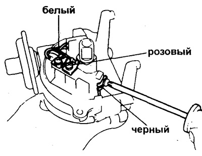
11 Install the switch.
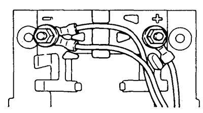
A) Secure the switch case with two screws. Connect the three wires to the switch terminals with three screws as shown in the figure.
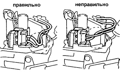
b) As shown in the figure, secure the wires of the ignition timing sensor induction coil with clamps to provide the necessary slack.
Attention: the wires must not touch the rotor of the ignition timing sensor and the distributor housing.
12. Install the ignition coil.
A) Install the gasket and ignition coil with four screws.
b) Connect the four wires to the switch terminals with two screws as shown in the figure.
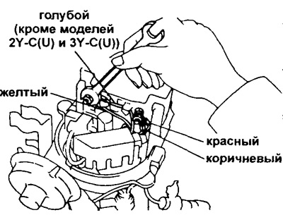
Attention:
- When connecting the wires to the ignition coil, lay them in the grooves laid on the surface of the ignition coil;
- Make sure the wires do not touch the ignition timing sensor rotor and the distributor housing.
13. Install the protective cover (dust deflector) switch.
14. Install the protective cover (dust deflector) ignition coils.
15. Establish a rotor of the gauge of the moment of ignition.
16. Install the distributor cap and high voltage wires.
Place a gasket in place of the distributor cap connector and secure the distributor cap with three bolts.
17. Install a new ring on the distributor housing, lightly lubricating it with engine oil.