
Remove the clamp from the main wiring harness in the engine compartment.
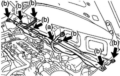
Pic. 2.198. Fastening of the top external panel of a cowl
Turn out 7 bolts of fastening and remove the top external panel of a cowl (pic. 2.198).
Remove the front right wheel
Remove the lower left engine shield.
Remove the #1 motor bottom guard.
Remove the lower right engine cover.
Remove the top radiator shroud.
Remove the cylinder head cover #2.
Remove coolant.
Remove the front exhaust pipe assembly.
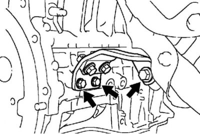
Pic. 2.199. Manifold Bracket Bolts
Turn out 3 bolts of fastening and remove an arm of a collector (pic. 2.199).
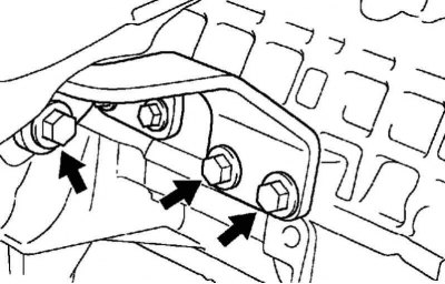
Pic. 2.200. Manifold Bracket No. 2 Bolts
Remove 3 bolts and remove manifold bracket #2 (pic. 2.200).
Remove the fan and alternator V-belt.
Remove the power steering pump assembly.
Remove the generator assembly.
Remove the right engine mount.
Remove the ignition coil assembly.
Remove the cylinder head cover.
Remove the V-ribbed belt tensioner assembly.
Remove the right engine mount bracket.
Remove the water pump assembly.
Remove the crank angle sensor.
Set the #1 cylinder piston to TDC on the compression stroke.
Remove the crankshaft pulley.
Remove the #1 chain tensioner assembly.
Remove the timing chain or belt drive cover.
Remove the timing chain or belt drive cover seal.
Remove the gear disk of the crankshaft angle sensor.
Remove the tensioner shoe and chain.
Remove the chain guide #1.
Disconnect the VSV valve connector.
Disconnect the engine harness clamp.
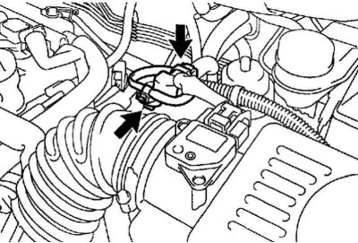
Pic. 2.201. Hoses for removing fuel vapors No. 1 and No. 3
Disconnect EVAP hoses #1 and #3 from VSV (pic. 2.201).
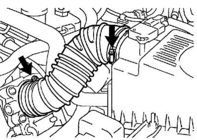
Pic. 2.202. No. 1 Air Filter Hose Clamps
Loosen the 2 fastening clamps and disconnect the No. 1 air filter hose (pic. 2.202).
Remove the oil dipstick.
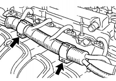
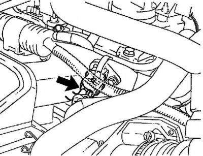
Pic. 2.203. Clamps of fastening of a plait of wires of the engine
Remove the 2 clamps of the engine wiring harness from the bracket (pic. 2.203).
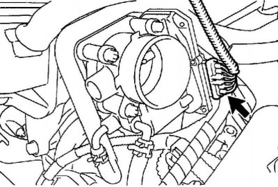
Pic. 2.204. Throttle Motor Connector
Disconnect the throttle motor connector (pic. 2.204).
Disconnect the coolant bypass hoses from the throttle body.
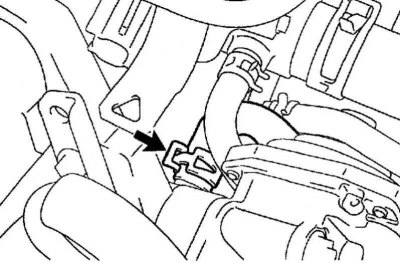
Pic. 2.205. Hose connecting to the intake manifold fitting
Disconnect the hose from the intake manifold that connects to the fitting (pic. 2.205).
Turn out 4 bolts, turn away 2 nuts and remove 2 arms of collars.
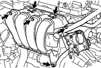
Pic. 2.206. intake manifold mounting
Remove intake manifold and throttle body (pic. 2.206).
Remove the gasket from the intake manifold.
Remove the oil camshaft control valve assembly.
Removing the camshaft
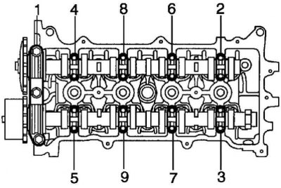
Pic. 2.207. The procedure for loosening the bearing cap bolts
In several steps, evenly loosen and unscrew the 19 bolts of the bearing caps, acting in the sequence shown in Figure 2.207.
Remove 9 bearing caps, then remove 2 camshafts from the cylinder head.
Disconnect the fuel supply line.
Removing the cylinder head
Disconnect the engine wiring harness.
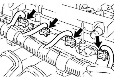
Pic. 2.208. Fuel injector connectors
Disconnect 4 fuel injector connectors (pic. 2.208).
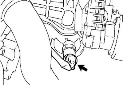
Pic. 2.209. Oil pressure sensor connector
Disconnect the oil pressure sensor connector (pic. 2.209).
Disconnect the crankshaft position sensor connector.
Disconnect the knock sensor connector.
Pic. 2.210. Camshaft position sensor connector
Disconnect the camshaft position sensor connector (pic. 2.210).
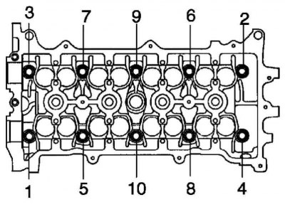
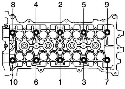
Pic. 2.211. Cylinder head bolt loosening sequence
In several steps, with a 10 mm allen key, evenly loosen and unscrew 10 cylinder head mounting bolts, acting in the sequence shown in Figure 2.211. Remove 10 cylinder head bolts and 10 flat washers (pic. 2.211).
Note. Be careful not to drop the washers into the cylinder head.
If the bolts are removed in the wrong sequence, the cylinder head may warp or break.
Remove the cylinder head.
Remove the cylinder head gasket.
Check of bolts of fastening of a head of the block of cylinders
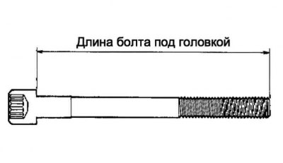
Pic. 2.212. Head bolt length
Using a caliper, measure the length of the cylinder head bolts from the seating surface of the head to the end of the threaded part (pic. 2.212).
- Nominal length: 146.8 - 148.2 mm.
- Maximum allowable length: 148.5 mm.
If the bolt length exceeds the maximum allowable length, replace the cylinder head bolt.
Installing the cylinder head gasket
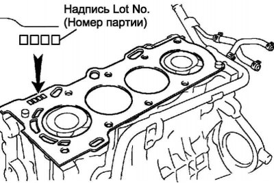
Pic. 2.213. Marking «Lot No.» cylinder head gaskets
Install a new cylinder head gasket on the surface of the cylinder block with a die «Lot No.» (Batch number) up (pic. 2.213).
Note. Install the gasket in the correct position.
Install the cylinder head carefully so as not to damage the gasket.
Installing the cylinder head
Apply a light coat of engine oil to the threads of the cylinder head bolts.
Note. Bolts of fastening of a head of the block of cylinders tighten in 2 steps.
Pic. 2.214. Cylinder head bolt tightening sequence
In several steps, with a 10 mm allen key, evenly tighten 10 cylinder head bolts with flat washers, acting in the sequence shown in Figure 2.214.
Tightening torque: 49 Nm.
Mark the front side of each of the cylinder head bolts with paint.
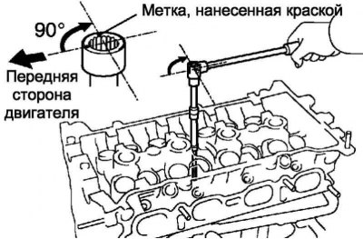
Pic. 2.215. Tighten the cylinder head bolts
Tighten the cylinder head bolts 90°in the sequence shown in the previous procedure (pic. 2.215).
Make sure the marks are rotated 90°from their original position.
Fix the drain pipe No. 1 of the cooling system with a bolt.
Tightening torque: 9.0 Nm.
Connect heater inlet hose A.
Connect the radiator inlet hose and engine wiring harness.
Connect the heated oxygen sensor connector.
Attach 2 engine ground wires.
Connect the connector of the radio and additional equipment.
Connect the coolant temperature sensor connector.
Connect the camshaft position sensor connector.
Connect the knock sensor connector.
Connect the crankshaft position sensor connector.
Connect the oil pressure sensor connector.
Attach 4 injector connectors.
Connect the fuel supply line.
Installation of camshafts
Apply a thin coat of engine oil to the camshaft journals.
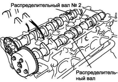
Pic. 2.216. Scheme of correct installation of camshafts
Establish 2 camshafts in a head of the block of cylinders, as it is shown in drawing 2.216.
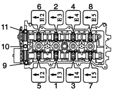
Pic. 2.217. The sequence of tightening the bearing cap bolts
Check up, whether labels which have to be turned to a forward part of the engine, and numbers of covers are correctly located, then tighten bolts in the sequence specified in drawing 2.217.
Tightening torque: 23 Nm for bearing cap no. 1, 13 Nm for bearing cap no. 3.
Install the variable valve timing control oil valve assembly.
Intake manifold installation
Install a new gasket on the intake manifold.
Install intake manifold and throttle body and secure with 2 brackets, 4 bolts and 2 nuts.
Tightening torque: 30 Nm.
Connect the union hose to the intake manifold.
Attach the No. 2 coolant bypass hose to the throttle body.
Connect the coolant bypass hose to the throttle body.
Connect the throttle motor connector.
Install the 2 engine wiring harness clamps to the bracket.
Note. Installation and assembly of other components is carried out in the reverse order of removal.