
Remove the lower right engine cover.
Remove the cylinder head cover #2.
Remove the fan and alternator V-belt.
Remove the crankshaft pulley.
Use a knife to cut the working edge of the gland.
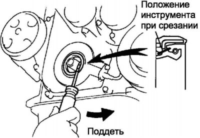
Pic. 2.176. Oil seal removal
Remove the oil seal with a screwdriver with a tape-wrapped blade (pic. 2.176).
Note. After removing the oil seal, check if the crankshaft is damaged. If damaged, sand the surface of the crankshaft with 400 grit sandpaper.
Apply multipurpose grease to the edge of the new oil seal.
Note. The seating surface of the seal must be free of sand, dirt and other foreign particles.
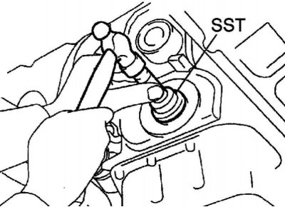
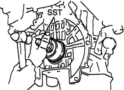
Pic. 2.177. Pressing in the stuffing box
Using tool SST 09223-22010 and a hammer, press in a new oil seal so that its surface is flush with the edge of the timing chain cover (pic. 2.177).
Note. Press the stuffing box strictly along the axis of the socket, without distortion.
Note. Remove excess grease from crankshaft.
Replacement of a back epiploon of a cranked shaft of the engine
Remove the manual transmission and clutch basket assembly.
Remove the clutch disc assembly.
Hold the crankshaft with SST 09960-10010.
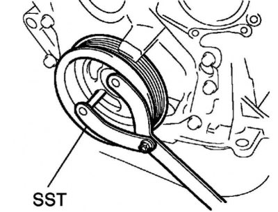
Pic. 2.178. Removing the flywheel
Remove 8 bolts and remove flywheel (pic. 2.178).
Use a knife to cut the working edge of the gland.
Pic. 2.179. Oil seal removal
Remove the oil seal with a screwdriver with a tape-wrapped blade (pic. 2.179).
Note. After removing the oil seal, check if the crankshaft is damaged. If damaged, sand the surface of the crankshaft with 400 grit sandpaper.
Apply multipurpose grease to the edge of the new oil seal.
Note. The seating surface of the seal must be free of sand, dirt and other foreign particles.
Pic. 2.180. Pressing in the stuffing box
Using tool SST 09223-15020, 09950-70010 and a hammer, press in the new oil seal so that its surface is flush with the edge of the rear oil seal cover (pic. 2.180).
Note. Press the stuffing box strictly along the axis of the socket, without distortion.
Note. Remove excess grease from crankshaft.
Hold the crankshaft with SST 09960-10010
Clean 8 bolts and 8 bolt holes.
Apply threadlocker to 2 or 3 threads of 8 bolts.
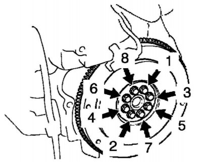
Pic. 2.181. Flywheel tightening sequence
In several steps, evenly, tighten 8 bolts, acting in the sequence shown in Figure 2.181.
Tightening torque: 49 Nm.
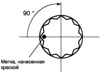
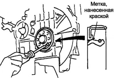
Pic. 2.182. Marking locations
Mark the bolts with paint, as shown in Figure 2.182.
Tighten the bolts 90°in the same sequence as when installing the bolts for the first time.
Make sure the marks are rotated 90°from their original position.
Install other components in the reverse order of removal.