
Pic. 2.113. Connecting the stroboscope sensor
Set the strobe sensor to the position shown in fig. 2.113.
Note. Use a stroboscope that registers the first signal.
Note. After checking, wrap the wiring harness with electrical tape.
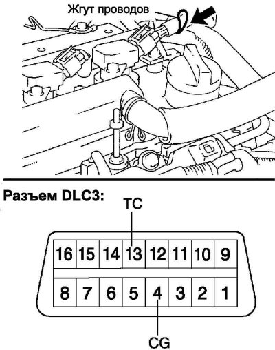
Close the terminals of the diagnostic connector DLC3 13 (TC) and 4 (CG) special jumper SST.
Note. Check the connector terminal numbers carefully before connecting. Shorting other terminals may damage the motor.
Turn the ignition ON (START).
Check ignition timing at idle.
Ignition timing: 8–12°to TDC
Note. Let the engine run at 1000-1300 rpm–1 for 5 seconds, then check that the speed has decreased to idle speed.
Disconnect the jumper from pins 13 (TC) and 4 (CG) DLC3 connector.
Check ignition timing at idle.
Ignition timing: 10–18°to TDC
Make sure that the ignition timing is increased immediately after the engine speed is increased.
Turn off the ignition (OFF).
Disconnect the stroboscope.
Install the cylinder head cover.