
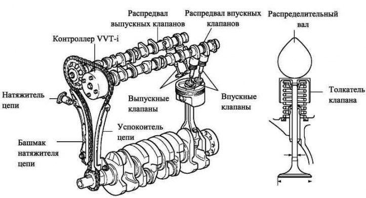
Pic. 2.11. valve mechanism
General information
The stroke of the valve lifters is increased, a design without shims and with an increased contact surface with the cam is used.
High power, low fuel consumption and low exhaust emissions are achieved through the use of an electronic variable valve timing system WT-i.
Maintenance recommendation
The valve clearance is adjusted by selecting the appropriate size tappets. Valve lifters are available in 35 sizes in 0.020mm increments, from 5.060mm to 5.740mm.
Table 2.17. Thickness of new pushers (mm)
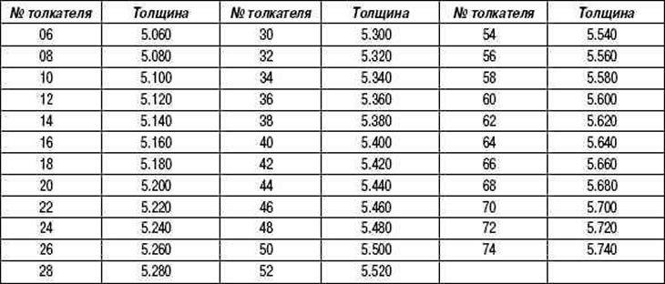
Table 2.18. Selection of adjusting washers for inlet valves
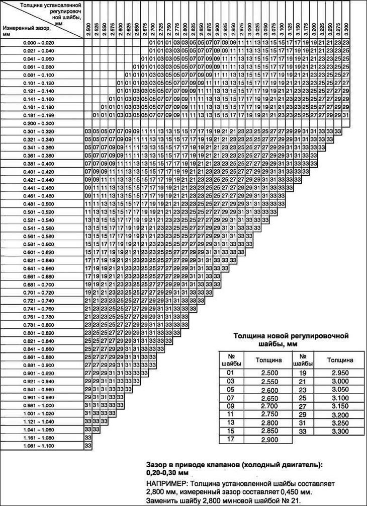
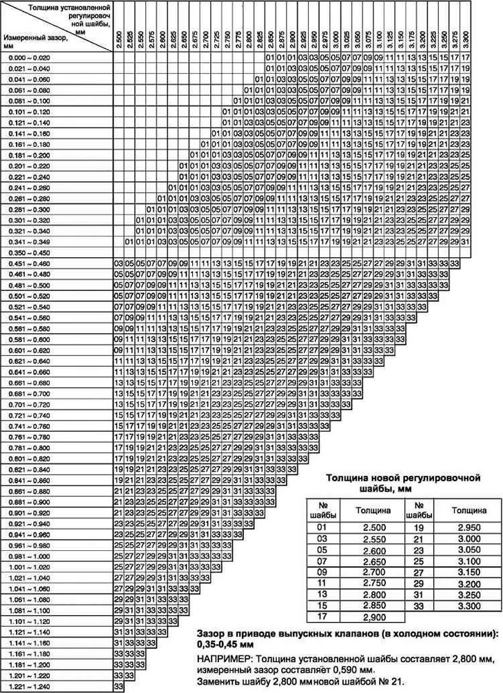
Table 2.19. Exhaust valve shim selection
Camshaft
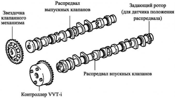
Pic. 2.12. Camshafts
The intake camshaft has a channel for supplying pressurized oil to the VVT-i electronic camshaft control system.
To change the intake valve timing, a VVT-i system controller is installed at the front end of the intake camshaft.
Valve chain drive and chain tensioner
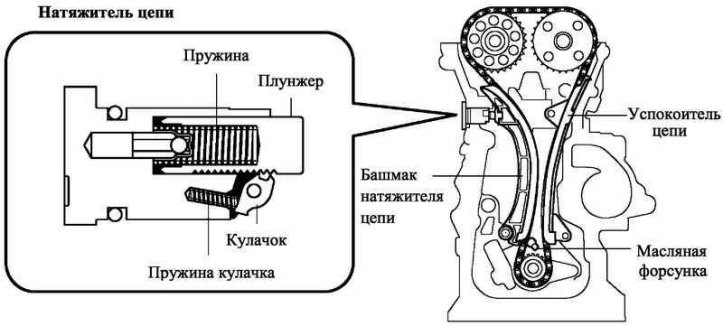
Pic. 2.13. Valve chain drive and chain tensioner
In order to reduce the size of the motor, a roller chain with a pitch of 8 mm is used in the valve train drive.
Lubrication of the valve train chain is carried out by an oil nozzle.
The chain tensioner uses a spring and oil pressure to create a constant force. The tensioner reduces noise during chain operation.
The tensioner has a ratchet mechanism.
To improve maintainability, a design was used that allows you to remove and install the tensioner without removing the chain cover.