
Note. In case of inconsistency with the data given on the VECI label, preference should be given to the latter.
General information
Ignition timing is measured in degrees of engine crankshaft angle and is important for firing spark plugs at a certain point on the compression stroke.
Ideally, if a spark from a spark plug would ignite the air-fuel mixture in the combustion chamber at the moment the piston passes the TDC compression stroke. In this case, the air-fuel mixture will burn and expand. The expanding gases will push the piston down in its stroke, thus rotating the crankshaft.
It takes a fraction of a second to completely ignite the working mixture. Therefore, in order to comply with the normal working process of combustion (complete combustion of the mixture) the engine needs some ignition advance. Lead is measured in degrees before TDC. If the engine advance is 7 degrees BTDC, this means that the spark plug should be energized when the crankshaft is 7 degrees BTDC on the first piston compression stroke. However, this is only true when the engine is idling.
If the crankshaft rotates faster, then the pistons move faster. Therefore, in order to completely burn the mixture, candles must ignite it even earlier. To meet these conditions, the ECU adjusts the ignition timing according to the increase in engine speed.
The electronic ignition timing control is known as ESA and is determined by the ECU program. By monitoring crankshaft speed, intake air mass, engine temperature, throttle position and other factors, the ECU microprocessor controls the ignition timing in all engine operating modes from cold start to full load. The system is simple, unregulated and reliable.
Examination
1. Warm up the engine to normal operating temperature.
2. Connect the OBD II scanner to the diagnostic connector located under the front panel on the driver's side.
3. Move the AT selector lever to position «N».
4. With the ignition off, connect the stroboscope according to the manufacturers instructions. Most modern stroboscopes are equipped with an autonomous battery. The inductive lamp sensor is installed on the BB wire of the spark plug of the first cylinder.
5. Spin the engine up to 2500 rpm for one and a half minutes and return the engine to idle (650 - 750 rpm).
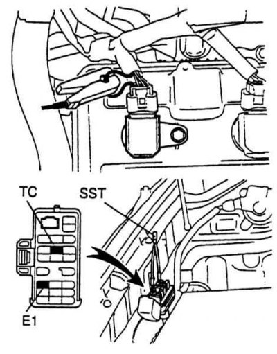
6. Using a jumper from a piece of wire, bridge the E1 and TE1 terminals on the DLC-1 diagnostic connector under the hood (refer to accompanying illustration).
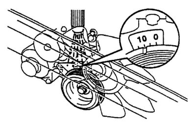
7. Check with a stroboscope that the ignition mark is within 5 - 15°before TDC at idle (refer to accompanying illustration).
8. Stop the engine and disconnect the stroboscope.