
Functional diagram of a typical charge system
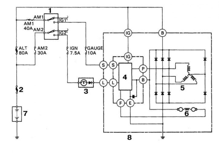
1 - Ignition switch; 2 - Main fusible link; 3 - Control lamp charge; 4 - Voltage regulator; 5 - Stator winding; 6 - Rotor winding; 7 - Battery; 8 - Generator
Charging system components include an alternator with a built-in maintenance-free voltage regulator, a charge warning light/indicator, a battery, protective fuses, and wiring connecting these components (refer to illustration above). The charging system provides electrical power to the ignition system, lighting and signaling devices, audio system and other on-board electrical consumers. The generator is driven by a belt drive from the crankshaft pulley and is mounted at the front of the engine. Additional information on the electrical connections of the components of the charging system can be found in the wiring diagrams (see Onboard electrical equipment).
The task of the voltage regulator is to limit the voltage generated by the generator within the specified limits. The regulator prevents circuit overloads and other unpleasant phenomena associated with power surges.
Fuses on the models under consideration replace fuses, differing from the latter in a greater current carrying capacity. The inserts are placed in the relay mounting block located in the engine compartment (see Onboard electrical equipment).
The charging system does not require regular maintenance. However, you should periodically check the condition of the alternator drive belt, battery, connecting wiring and its terminal connections (see chapter Vehicle settings and routine maintenance).
The charge control lamp mounted in the instrument panel briefly turns on when the ignition key is turned to the ON position and should go out immediately after the engine is started. Failure of the lamp to turn off indicates a malfunction in the charge system. On some models, a voltmeter is additionally installed in the instrument panel, which allows the driver to timely monitor deviations of the on-board voltage from the norm. If the voltmeter readings are outside the allowable range, the charge system should be checked (see Section Checking the state of the charge system).
When docking the terminal connections of electrical circuits of vehicles equipped with an alternator, special precautions should be observed:
- a. When connecting the battery wiring to the generator, never reverse the polarity;
- b. Before using electric arc welding for body repairs, disconnect the electrical wiring from the terminals of the generator and the battery;
- c. Never start the engine with the charger connected to the battery;
- d. Always disconnect both wires from the battery before charging from an external power source (first negative);
- e. Avoid getting hands, hair and loose clothing in contact with the rotating alternator drive belt during engine running checks;
- f. Remember that the generator is connected directly to the battery and its overloads and short circuits can ignite the wiring and cause a fire;
- g. Before steam cleaning the engine compartment, wrap the generator in a plastic bag, which should then be securely fastened with rubber bands.