
Telescopic inside diameter gauge
Cleaning
Attention! The plugs of the channels of the cooling system are tightly pressed into the cylinder block.
1. Remove lids with liners, label them and store separately.
2. Carefully clean the block of seal residue.
3. Drill out block plugs (it's almost impossible to get them out), drive the threads and install new plugs when assembling.
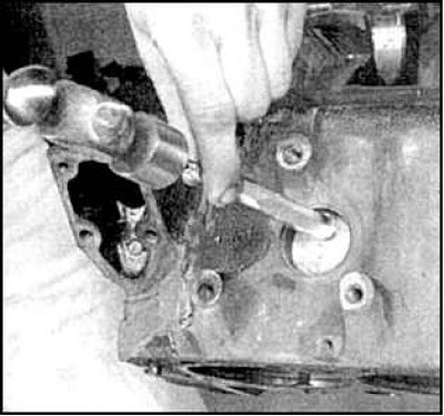
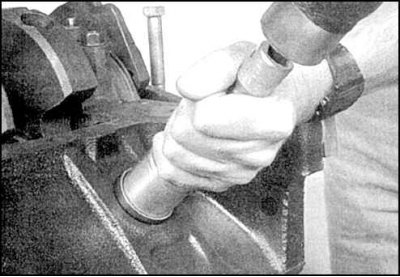
4. Knock out the plugs of the cooling channels.
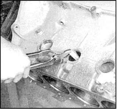
5. Remove the plugs with pliers.
6. If the block is very dirty, clean all channels with a jet of steam and compressed air (it is recommended to perform in a car service), wash the outside of the unit with detergent. Drive all threaded holes, clean and blow with compressed air. Dry the block and lubricate.
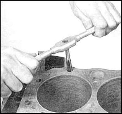
7. Drive all the threads of the cylinder block, thereby clearing the dirt.
8. Establish covers of radical bearings, tighten bolts by hand.
9. Press in new plugs without distortions, having previously lubricated them with Permatex N2 sealant. Wrap on the same sealant new plugs of oil channels. Tighten the plugs tightly.
Examination
Numbers of size groups of pistons in each of the cylinders
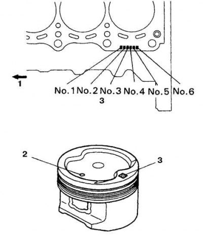
1. To the front of the engine; 2. Orientation mark (towards the front of the engine); 3. Marks 1, 2 or 3
1. When external defects are found (cracks and chips), repair or replace the unit. It is recommended to check for internal defects in the cylinder block, for which it is necessary to hand over the block to a car service.
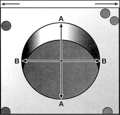
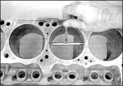
2. Check the condition of the surface, the clearance between the piston and the cylinder, the ovality and taper of the cylinders by measuring the diameter in three planes, in directions parallel and perpendicular to the axis of the block. If the results differ from the standard, then the cylinders should be bored. After boring the block, pistons and rings of repair sizes will be needed.
3. In the absence of an inside gauge, the gap can be checked with special probes about 300 mm long. Insert the piston into the appropriate cylinder and check the piston stroke by running a feeler gauge over the main friction surfaces (in the direction of the finger and perpendicular to the finger).
4. The gap is determined by the thickness of the feeler gauge, at which the piston moves in the cylinder under moderate force. If the piston fails or slips, then the clearance is above normal and the piston must be replaced and the cylinder re-grinded. If the piston sticks when the dipstick is near BDC and slips when the dipstick is near TDC, then the taper of the cylinder is too high. If, when the piston is turned in a cylinder with a probe laid, the piston sticks, then the ovality of the cylinder exceeds the norm.
5. Standard diameter (size group) 1FZ-FE engine piston is identified by the marking on the piston head (groups 1, 2 or 3, see fig. Numbers of size groups of pistons in each of the cylinders). The number on the piston must match the number on the block corresponding to that cylinder.
6. If the condition of the cylinders is acceptable, the wear of the cylinder and the clearance between the cylinder and the piston do not exceed the established norms, then the cylinders only need to be honed (see subsection 3.3.7.6).
7. For a significant part of the engines, pistons and liners are provided (crankshaft and camshaft) repair sizes. On the cylinder blocks of these engines there are letters.