
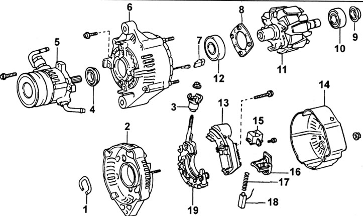
Generator disassembly
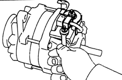
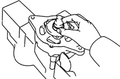
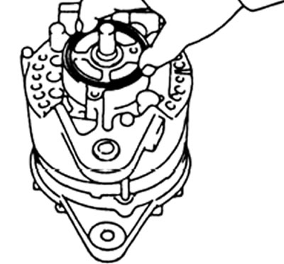
1. Remove the vacuum pump and O-ring by unscrewing the three bolts.
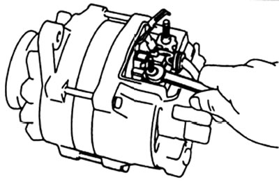
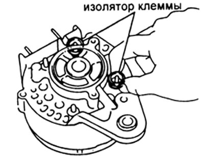
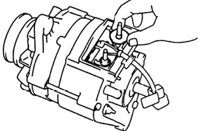
2. Remove the brush holder cover by unscrewing the two nuts, terminal insulator, rubber washer, wire lock, brush holder and insulating washer.
3. Remove the brush holder.
A) Disconnect the lead wire from the terminal "IN".
b) Remove the nut and brush holder.
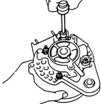
4. Loosen the three through screws and remove the alternator cover from the rectifier side.
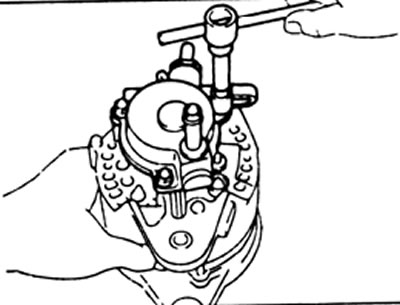
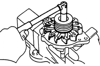
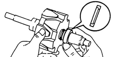
5. Remove the pulley and fan.
A) Secure the rotor in a vise.
b) Remove the pulley nut, spring washer, pulley, fan and spacer.
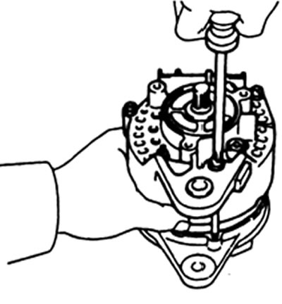
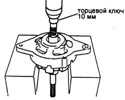
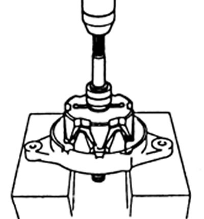
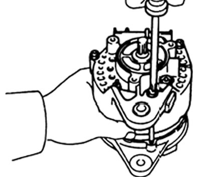
6. Remove the rotor.
A) Using a 10mm socket wrench and a press, press out the rotor.
b) Remove spacer ring and circlip from rotor shaft.
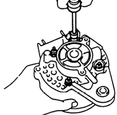
7. Remove the generator cover from the rectifier side.
A) Remove four nuts and two terminal insulators.
b) Remove the generator cover from the rectifier side.
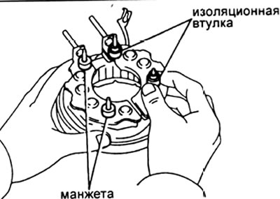
V) Remove the two terminal bushings and collars from the rectifier block studs.
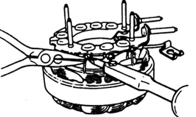
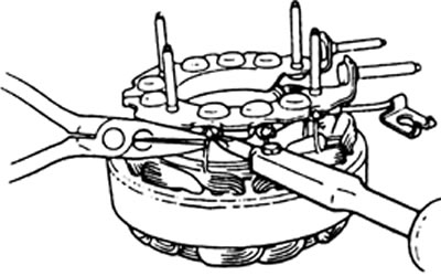
8. Remove the rectifier block.
While holding the stator winding lead with needle nose pliers, unsolder the leads.
Caution: Do not allow the diodes to heat up.
Rotor check
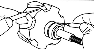
1. Check for an open in the field winding.
Using an ohmmeter, measure the resistance between the slip rings.
Rated resistance - 3.9-4.1 ohms
If resistance goes to infinity (those. open circuit) - replace the rotor.
2. Check if the excitation winding is shorted to "mass".
Using an ohmmeter, measure the resistance between the rotor pole and the slip ring.
If resistance is 0 (circuit is closed), then replace the rotor.
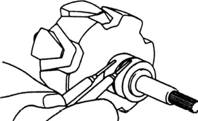
3. Check slip rings.
A) Check the working surfaces of the slip rings. They should not have scuffs or chips.
b) Using a caliper, measure the diameter of the slip rings.
Nominal diameter - 32.3 - 32.5 mm
Minimum allowable - 32.1 mm
If the diameter of the slip rings is less than the minimum allowable, then replace the rotor.
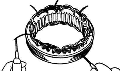
Stator check
1. Check for an open in the stator winding.
Using an ohmmeter, measure the resistance between the terminals of the stator winding coils.
If resistance goes to infinity (those. open circuit) - then replace the stator.
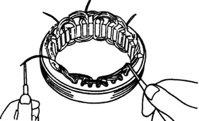
2. Check if the stator winding is shorted to "mass".
Using an ohmmeter, measure the resistance between the stator housing and the stator coil leads. If the resistance is "0" (those. circuit is closed) - then replace the stator.
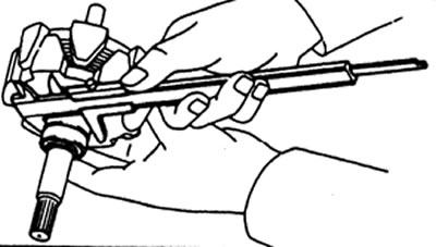
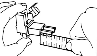
Checking the brushes
1. Measure the length of the protruding part of the brushes.
Rated - 20.0 mm
Minimum allowable - 5.5 mm
If the length of the protruding part is less than the minimum - allowable value, then replace the brushes.
2. Replacement of brushes (if necessary),
A) Unsolder the brush wire from the brush holder lead and remove the brush and brush spring.
b) Pass the wire through the hole in the brush holder and insert the brush into the brush holder.
V) Solder the brush wire to the brush holder lead so that the protruding length of the brush matches the nominal value given above.
G) Make sure the brushes move freely without binding.
d) Cut off the rest of the wire.
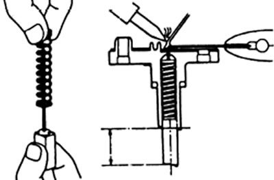
e) Apply insulating paint to the solder points.
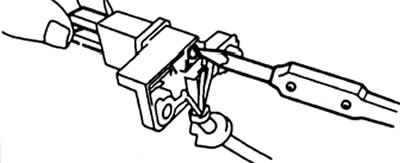
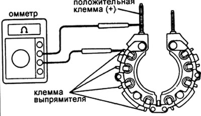
Rectifier unit check
1. Checking the positive valve.
A) Connect the negative tester (probe) ohmmeter to the positive terminal of the rectifier unit, and the positive probe (probe) connect in series to each of the other three outputs.
Check for conductivity (closed circuit) in all three dimensions.
b) Reverse the polarity of the tester probes and repeat the procedure of paragraph (A). Make sure the circuit is open in all three dimensions (resistance tends to infinity).
If the conditions are not met, replace the rectifier unit.
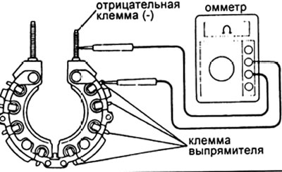
2. Checking the negative valve.
A) Connect one probe (probe) ohmmeter to the negative terminal of the rectifier unit, and the second probe (probe) connect in series to each of the other three outputs. Check for conductivity (closed circuit) in all three dimensions.
b) Reverse the polarity of the tester probes and repeat the procedure of paragraph (A). Make sure the circuit is open in all three dimensions (resistance tends to infinity).
If the conditions are not met, replace the rectifier unit.
Bearing check
1. Check the front bearing for roughness and wear.
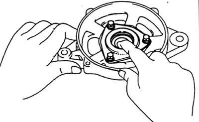
2. If necessary, replace the front bearing.
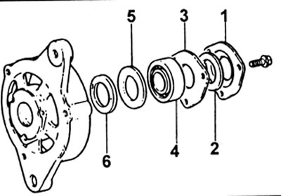
A) Remove three bolts and the following items:
- (1) felt cover,
- (2) felt,
- (3) fixing plate,
- (4) bearing,
- (5) felt cover,
- (6) felt.
b) Using three bolts, install the following items:
- (1) felt;
- (2) felt casing;
- (3) new bearing;
- (4) fixing plate;
- (5) felt;
- (6) felt casing;
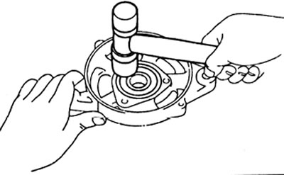
If necessary, fit a new bearing with light blows from a plastic-faced hammer.
Generator Assembly
1. Install the rectifier unit on the stator.
Hold the stator winding lead with needle nose pliers while soldering the leads.
Attention: do not allow the diodes to heat up.
2. Install the generator cover on the rectifier unit.
A) Place two grommets on the positive studs (+) rectifier block.
b) Place two cuffs on negative studs (—) rectifier block.
V) Place the alternator cover on the side of the rectifier box onto the rectifier box.
G) Check that the wires of the generator cover are not touching.
d) Place two terminal insulators on the positive studs of the rectifier block.
e) Tighten four nuts.
3. Install the rotor on the generator cover on the drive side.
A) Install the circlip into the groove of the rotor shaft.
b) Slide the spacer ring onto the rotor shaft.
V) Using a press, press in the rotor.
4. Install fan and pulley.
A) Secure the rotor in a vise.
b) Slide the spacer collar onto the rotor shaft.
V) Slide the fan, pulley and spring washer onto the rotor shaft.
G) Install the nut.
Tightening torque - 88 N.m
5. Install the alternator cover on the rectifier side with three through screws.
6. Check up smoothness of rotation of a rotor.
7. Install the brush holder.
A) Install the brush holder with nut.
b) Connect the lead wire to the terminal "IN".
8. Install the brush holder cover,
A) Place on terminal "IN" insulating washer.
b) Install the brush holder cover on the generator cover from the side of the rectifier unit.
V) Place the terminal washer and rubber washer on the terminal "IN".
G) Install the two nuts along with the alternator connector.
9. Install the vacuum pump.
A) Place a new O-ring on the alternator cover on the rectifier side.
b) Install the vacuum pump with three bolts.
Tightening torque - 7.8 N.m