
Note:
- This section contains only technical data and design differences.
- The disassembly, inspection and assembly procedures for the R150F and R151F gearboxes are the same as for the G52 gearbox, with design differences.
- Follow assembly drawings.
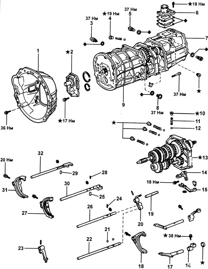
Gearboxes R150F and R151F. 1 - clutch housing; 2 - the holder of the input shaft bearing; 3 - reversing light switch; 4 - threaded plug; 5 - restrictive pin; 6 - gear lever cover; 7 - transfer box adapter; 8 - cork; 9 - gearbox housing; 10 - threaded plug; 11 - spring; 12 - ball; 13 - intermediate support; 14 - backstage bracket for reverse gear engagement; 15 - backstage switch on the reverse gear; 16 - gear lever housing; 17 - gear lever shaft; 18 - fork No. 3 gear shifting; 19 - rod No. 5 gear shift; 20 - head of the reverse gear engagement rod; 21 - blocking ball; 22 - rod No. 4 gear shift; 23 - reverse gear engagement fork; 24 - blocking pin No. 4; 25 - blocking pin No. 3; 26 - rod No. 3 gear shifting; 27 - fork No. 1 gear shift; 28 - blocking pin No. 2; 29 - blocking pin No. 1; 30 - rod No. 1 gear change; 31 - fork No. 2 gear shift; 32 - rod No. 1 gear shift.
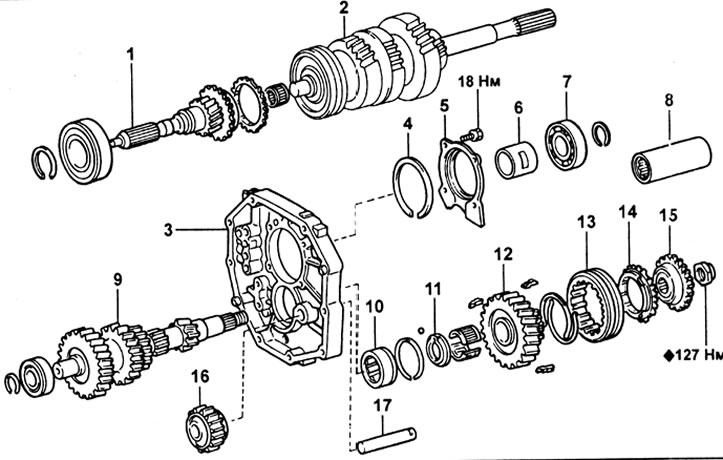
Gearboxes R150F and R151F (continuation).1 - input shaft; 2 - secondary shaft; 3 - intermediate support; 4 - retaining ring; 5 - the holder of the rear bearing of the secondary shaft; 6 - spacer sleeve; 7 - rear bearing of the secondary shaft; 8 - spacer sleeve; 9 - intermediate shaft; 10 - bearing; 11 - thrust washer; 12 - gear wheel of the fifth gear of the intermediate shaft; 13 - synchronizer clutch No. 3; 14 - synchronizer ring; 15 - fifth gear synchronizer hub; 16 - intermediate gear of reverse gear; 17 - shaft of the intermediate gear of the reverse gear.
Input shaft
1. Checking the clearance between the synchronizer ring and gear.
Normal gap - 0.8-1.6 mm
Minimum clearance - 0.6 mm
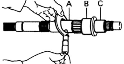
2. Selection of the retaining ring when replacing the input shaft bearing.
| Tags | Thickness, mm |
| A | 2,10-2,15 |
| IN | 2,15-2,20 |
| WITH | 2,20 - 2,25 |
| D | 2,25 - 2,30 |
| E | 2,30 - 2,35 |
| F | 2,35 - 2,40 |
| G | 2,40 - 2,45 |
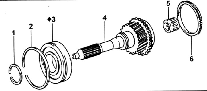
Input shaft for R150F and R151F gearboxes. 1, 2 - retaining ring; 3 - bearing; 4 - input shaft; 5 - needle bearing; 6 - synchronizer ring.
Output shaft
1. Checking the axial clearance of the output shaft gears.
First gear:
- Normal clearance - 0.10 - 0.45 mm
- Maximum clearance - 0.55 mm
Second and third gears:
- Normal clearance - 0.10 - 0.25 mm
- Maximum clearance - 0.30 mm
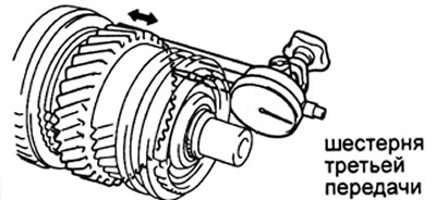
2. Checking the radial clearance of the output shaft gears.
Normal Clearance:
- 1st gear - 0.020 - 0.073 mm
- 2nd and 3rd gears - 0.015-0.068 mm
- Maximum clearance - 0.16 mm
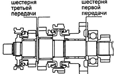
3. Checking the thickness of the edges of the secondary shaft.
Minimum thickness - 4.70 mm
4. Checking the outer diameter of the main shaft journals.
Minimum Diameter:
- 1st gear - 38.860 mm
- 2nd gear - 46.860 mm
- 3rd gear - 37, 860 mm
5. Checking the runout of the output shaft.
Maximum runout - 0.06 mm
6. Checking the gap between the synchronizer ring and the output shaft gear.
Normal clearance - 0.8-1.6 mm
Minimum clearance - 0.6 mm
7. Checking the gap between the synchronizer clutch and the shift fork.
Maximum clearance - 1.0 mm
8. When assembling the output shaft:
A) Retaining ring selection (№1).
| Label | Thickness, mm |
| A | 1,80-1,85 |
| IN | 1,85-1,90 |
| WITH | 1,90-1,95 |
| D | 1,95-2,00 |
| E | 2,00 - 2,05 |
| F | 2,05-2,10 |
| G | 2,10-2,15 |
b) Checking the axial clearance of the third gear.
Normal clearance - 0.10 - 0.25 mm
V) Retaining ring selection (№2).
| Label | Thickness, mm |
| A | 2,30 - 2,35 |
| IN | 2,35 - 2,40 |
| WITH | 2,40 - 2,45 |
| D | 2,45-2,50 |
| E | 2,50-2,55 |
| F | 2,55-2,60 |
| G | 2,60-2,65 |
G) Checking the axial clearance of the gears of the first and second gears after installing the bearing.
Normal Clearance:
- 1st gear - 0.10 - 0.45 mm
- 2nd gear - 0.10-0.25 mm
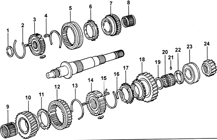
Output shaft for R150F and R151F gearboxes.1 - retaining ring, 2 - synchronizer spring, 3 - synchronizer hub No. 2, 4 - cracker, 5 - synchronizer clutch No. 2, 6 - synchronizer ring, 7 - third gear, 8 - needle bearing, 9 - needle bearing, 10 - gear of the second gear, 11 - synchronizer ring, 12 - synchronizer clutch No. 1 (reverse gear), 13 - synchronizer spring, 14 - synchronizer hub No. 1, 15 - cracker, 16 - retaining ring, 17 - synchronizer ring, 18 - first gear, 19 - spacer sleeve, 20 - needle bearing, 21 - pin, 22 - thrust washer, 23 - bearing, 24 - fifth gear.
Intermediate shaft and reverse idler gear
1. Checking the radial clearance of the fifth gear.
Normal clearance - 0.015 - 0.068 mm
Maximum clearance - 0.16 mm
2. Checking the outer diameter of the journal of the intermediate shaft.
Minimum diameter - 27.860 mm
3. Checking the clearance between the synchronizer ring and gear.
Normal clearance - 0.8 - 1.6 mm
Minimum clearance - 0.6 mm
4. Checking the gap between the synchronizer clutch and the shift fork.
Maximum clearance - 1.0 mm
5. Checking the gap between the intermediate reverse gear and the backstage engagement pin.
Normal clearance - 0.05 - 0.25 mm
Maximum clearance - 0.5 mm
6. Checking the radial clearance of the intermediate gear of the reverse gear.
Normal clearance - 0.040 - 0.082 mm
Maximum clearance - 0.13 mm
7. Selection of the retaining ring when replacing the front bearing of the intermediate shaft.
| Label | Thickness, mm |
| A | 2,00-2,05 |
| IN | 2,05-2,10 |
| WITH | 2,10-2,15 |
| D | 2,15-2,20 |
| E | 2,20-2,25 |
| F | 2,25-2,30 |
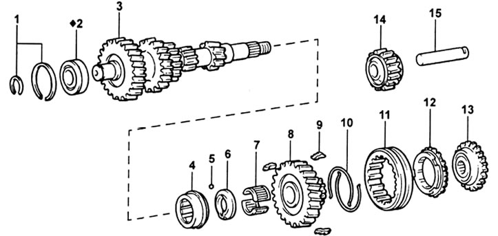
Intermediate shaft for R150F and R151F gearboxes. 1 - retaining ring, 2 - front bearing, 3 - intermediate shaft, 4 - bearing, 5 - ball, 6 - thrust washer, 7 - needle bearing, 8 - fifth gear, 9 - synchronizer cracker, 10 - synchronizer spring, 11 - synchronizer clutch No. 3, 12 - synchronizer ring, 13 - synchronizer hub No. 3 (fifth gear), 14 - intermediate gear of reverse gear, 15 - shaft of intermediate gear of reverse gear.
Main shaft bearing holder
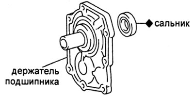
When replacing the input shaft bearing retainer seal.
Depth of pressing the stuffing box - 12.2 - 13.2 mm
Gearbox assembly
1. Installation of parts on an intermediate support.
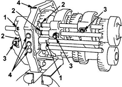
Installation locations. 1 - pins, 2 - retaining rings, 3 - fork bolts, 4 - threaded plugs.
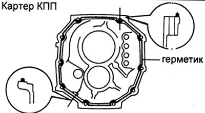
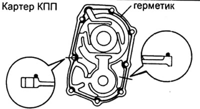
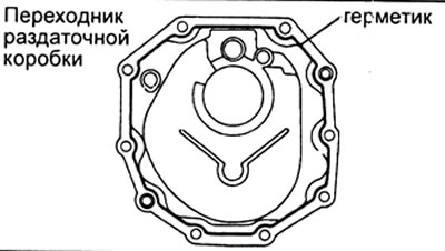
2. Application of sealant.
Note: Remove old sealant. Avoid getting oil on the contact surfaces.
A) When installing the gearbox housing.
b) When installing the input shaft bearing holder.
V) Installing the transfer box adapter.
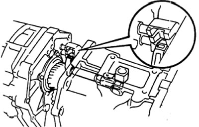
3. Connecting the shift lever shaft.
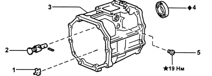
Transfer box adapter (Gearboxes R150F and R151F). 1 - oil receiver, 2 - reverse gear locking pin, 3 - transfer case adapter, 4 - stuffing box, 5 - plug.