
Ball joints
1. Check the lower ball joint for excessive play.
A) Place the front of the car on stands.
b) Check that the front wheels are in the straight ahead position and depress the brake pedal as far as it will go.
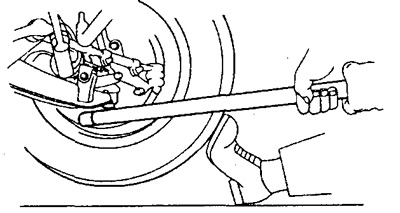
V) Rock the lower arm up and down to check for ball joint vertical play.
- Maximum vertical play of the lower ball joint - 2.3 mm
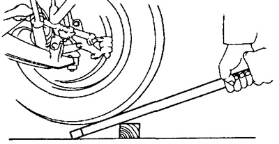
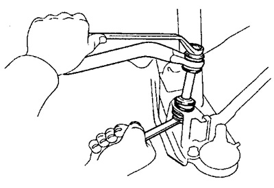
2. Check the upper ball joint for excessive play.
Rock the front wheel up and down to check for vertical ball joint play.
- Maximum vertical play of the upper ball joint - 2.3 mm
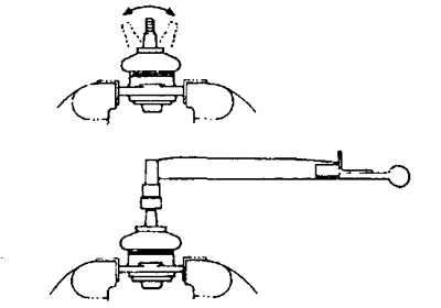
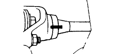
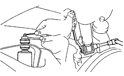
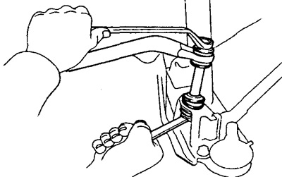
3. Check the ball joint.
A) Remove the ball joint.
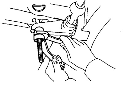
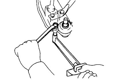
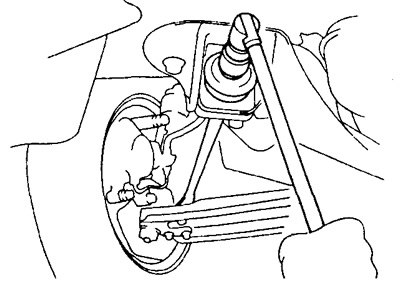
b) As shown in the figure, click the ball joint pin back and forth five times until the nut is installed.
V) Using a torque wrench, continuously rotate the ball stud on the nut one revolution in 2 to 4 seconds, then measure the torque at the fifth revolution.
- Torque - 1.5 - 3.0 Nm
Removing ball joints
1. Remove a rotary fist.
2. Remove the lower ball joint from the lower arm.
3. Remove the upper ball joint from the upper arm.
Installing ball joints
1. Install the upper ball joint on the upper arm.
- Tightening torque - 32 Nm
2. Install the lower ball joint on the lower arm.
Torque:
- External - 67 Nm
- Internal - 88 Nm
3. Establish a rotary fist.
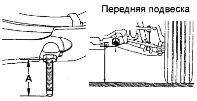
Removing the torsion bar
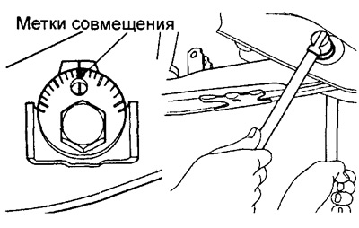
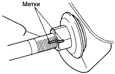
1. Remove the boot and mark the torsion bar, torsion arm and escapement arm.
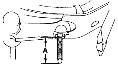
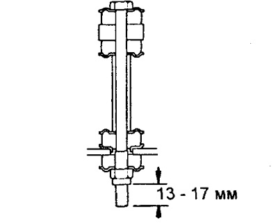
2. Loosen the locknut and measure the protruding end "A" bolts as shown.
Note: Use this measurement as a reference when adjusting body height.
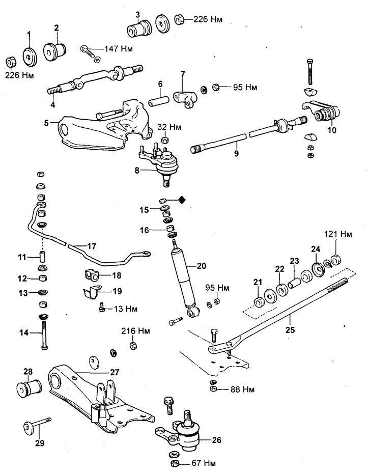
Front suspension (Dyna 100).
1, 24 - Washer,
2 - Front bushing,
3 - Rear bushing,
4 - Axis of the upper arm,
5 - Upper lever,
6 -; 11 -; 12 -; 16 -; 18 -; 22 -; 23 -;
28 - Bushing,
7 - Twisting lever,
8 - Upper ball joint,
9 - Torsion,
10 - Anchor lever,
13 -; 15 - Retainer,
14 - Bolt,
17 - Anti-roll bar,
19 - Bracket,
20 - Shock absorber,
21 - Front nut,
25 - Stretching,
26 - Lower ball joint,
27 - Lower arm,
29 - Adjusting cam.
b) Loosen the adjusting nut, remove the anchor arm and torsion bar.
Torsion bar installation
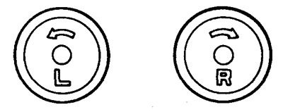
Warning: There is a mark on the end of the torsion bar. When installing, do not confuse the torsion bars.
1. Install torsion bar and anchor arm. (When installing the old torsion bar)
A) Apply grease to the torsion bar splines.
b) Aligning the marks, install the torsion bar on the twisting lever.
V) Aligning the marks, install the anchor lever on the torsion bar.
G) Tighten the adjusting nut so that the bolt protrudes exactly the same amount as before removal.
(When installing a new torsion bar)
A) Remove the wheel.
b) Apply grease to the torsion bar splines.
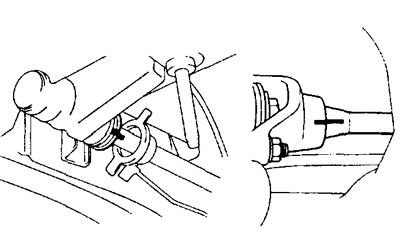
V) Install one end of the torsion bar on the twist arm.
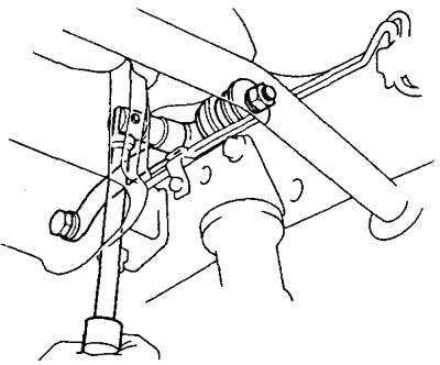
G) Install the torsion bar on the other side into the anchor arm as shown in the figure.
d) Screw on the nut without tightening it.
e) Make sure the top arm is in a horizontal position.

h) Tighten the adjusting nut.
and) Rock the body up and down a few times to stabilize the suspension.
To) Adjust body height by turning the adjusting nut.
2. Tighten the locknut and install the boot.
Removing the lower control arm and shock absorber
1. Remove the brake caliper, hub and dust cover.
2. Remove shock absorber.
3. Disconnect the anti-roll bar.
4. Disconnect the rack from the lower arm.
5. Remove the lower ball joint.
A) Remove the cotter pin and unscrew the nut.
b) Disconnect the ball joint from the steering knuckle and remove it.
Note: Do not damage the boot.
6. Remove the lower arm.
A) Mark the adjusting cam.
b) Remove the adjusting cam and nut and remove the lower arm.
Replacing the bushing of the lower arm
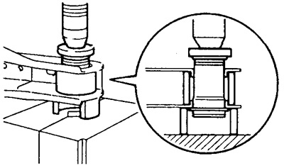
1. Using a drift and a press, remove the lower arm bushing.
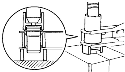
2. Using a drift and a press, install a new lower arm bushing. Note: Do not apply grease to the bushing.
Installing the lower control arm and shock absorber
1. Install the lower arm, then align the marks and screw on the nut without tightening it.
2. Install the lower ball joint on the lower arm.
Torque:
- External - 67 Nm
- Internal - 88 Nm
3. Screw the stand to the lower arm.
- Tightening torque - 88 Nm
4. Screw on the anti-roll bar.
5. Connect the ball joint to the steering knuckle.
A) Press down on the lower arm and strut and insert the ball joint into the steering knuckle.
b) Tighten the nut and install the cotter pins.
- Tightening torque - 142 Nm
6. Install shock absorber.
A) Install the shock absorber to the bottom bracket.
- Tightening torque - 95 Nm
b) Screw the shock absorber to the top bracket.
- Tightening torque - 25 Nm
7. Install the steering knuckle arm, dust cover, hub and brake caliper.
8. Tighten the adjusting cam nut.
A) Remove the stands and rock the body up and down a few times to stabilize the suspension.
b) Tighten the adjusting cam nut.
- Tightening torque - 216 Nm
9. Check up adjustment of corners of installation of forward wheels.
Removing the upper arm
1. Remove the torsion bar.
2. Disconnect the top part of the brake cylinder.
3. Disconnect the top spherical joint from a rotary fist.
A) Remove the cotter pin and unscrew the nut.
b) Disconnect the ball joint from the steering knuckle.
Note: Be careful not to damage the joint boot and brake hose.
V) Hang the steering knuckle, hub and brake cylinder on a rope.
4. Turn away bolts and remove the top lever.
Note: Do not damage the brake pipe.
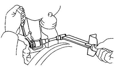
Upper Arm Bushing Replacement
1. Remove the twist arm.
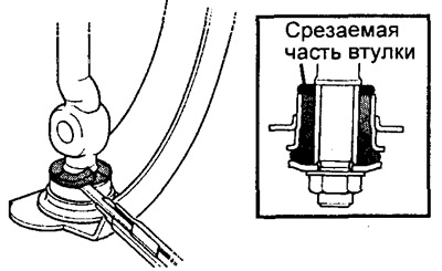
2. Remove the front bushing.
A) Cut off part of the sleeve as shown in the figure.
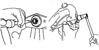
b) Using a hammer and chisel, chisel and loosen the nut.
V) Remove the front bush, then remove the upper arm axle.

3. Remove the rear bushing.

4. Install rear hub.
A) Install the upper arm axle.
b) Install a new bushing.
Note: Do not apply grease to the bushing.
5. Install new front bushing.
6. Install the top pivot pin.
A) Install washers and new nuts.
Note: Place the upper arm and its axle in the position shown in the figure, then tighten the nuts.
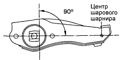
b) Tighten the shaft nuts.
- Tightening torque - 226 Nm
Note: Tighten the rear nut first, then the front nut.
V) Using a hammer and chisel, caulk the nut.
7. Screw the twist arm to the upper arm.
- Tightening torque - 95 Nm
Top arm installation
1. Screw the upper arm to the frame.
- Tightening torque - 147 Nm
2. Install the upper ball joint.
A) Install the ball joint to the upper arm.
- Tightening torque - 32 Nm
b) Jack up the lower control arm and insert the upper ball joint into the steering knuckle.
- Tightening torque - 142 Nm
V) Tighten the nut and install a new cotter pin.

3. Screw on the top of the brake cylinder.
- Tightening torque - 39 Nm
4. Install the torsion bar.
5. Check up corners of installation of forward wheels.
Stretch Removal
1. Mark the brace and nut.
2. Turn away a back nut of an extension.
3. Unscrew the nut securing the brace to the lower arm and remove the brace.
Stretch installation
(When reusing stretch marks)
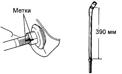
1. Wrap the nut, aligning the marks. (When using a new stretch)
1. Screw the nut to size 390 mm.
2. Install the brace on the bracket, and) Install the washer and bushing on the brace and install the brace to the bracket.
b) Install the bushings and washer on the extension.
V) Screw on the rear nut without tightening it.
3. Screw the brace to the lower arm.
- Tightening torque - 88 Nm
4. Tighten the rear nut.
A) Remove the stands and rock the body up and down a few times to stabilize the suspension.
b) Tighten the rear nut.
- Tightening torque - 121 Nm
5. Check the front wheel alignment.
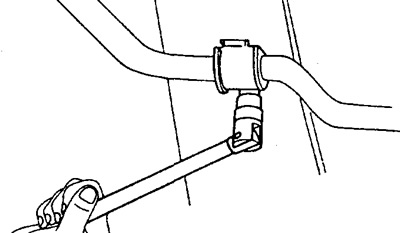
Removing the stabilizer bar
1. Separate the stabilizer from the lower arm.
A) Unscrew the nuts, remove the bushings securing the stabilizer on both sides to the lower arm and disconnect the stabilizer.
b) Remove the stabilizer bushings and brackets and remove the stabilizer.
Installation of the anti-roll bar
1. Install the brackets securing the stabilizer to the frame and tighten the bolts without tightening.
2. Connect the stabilizer to the lower arm, install the bolts, bushings and new nuts as shown. Tighten nuts.
3. Tighten the bracket mounting bolts.
- Tightening torque - 13 Nm