Rotor
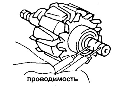
1. Using an ohmmeter, measure the resistance between the slip rings of the collector.
- Resistance (cold) should be from - 2.8 ohms to 3.0 ohms
If the field winding is open (resistance tends to infinity), then replace the rotor.
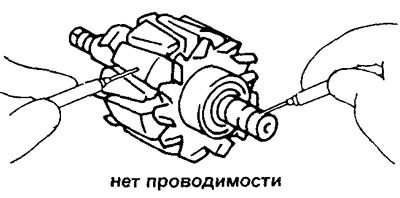
2. Check whether the excitation winding is shorted to ground.
Using an ohmmeter, measure the resistance between the slip ring and the rotor pole piece. The resistance should tend to infinity, otherwise replace the rotor.
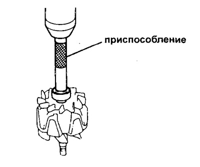
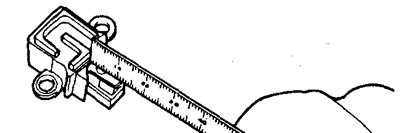
3. Check the outer surfaces of the slip rings. In the presence of roughness, scratches, replace the rotor. Using a caliper, measure the outside diameter of the manifold slip rings.
- Nominal diameter - 14.2-14.4 mm
- The minimum allowable diameter is 12.8 mm
If the diameter is less than the minimum value, replace the rotor.
Stator
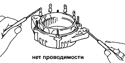
1. Using an ohmmeter, check all starter coils for open circuits. In the absence of conduction (resistance tends to infinity) replace the stator.
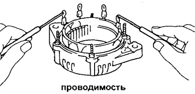
2. Check whether the turns of the stator winding are shorted to ground. Using an ohmmeter, measure the resistance between the winding wires and the generator cover on the drive side (stator). If there is continuity, i.e. the winding shorts to ground, replace the stator.
Brushes
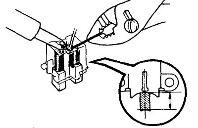
1. Measure the length of the protruding part of the brushes.
- Nominal length - 10.5 mm
- The minimum allowable length is 1.5 mm
If the length of the protruding part of the brushes is less than the minimum, replace the brushes.
2. Replace brushes if necessary.
A) Unsolder the brush wire and remove the brush and spring.
b) Pass the brush wire (new) through the spring and brush holder. Install the new brush with the spring into the brush holder.
V) Solder the brush wire to the brush holder lead so that the length of the protruding part of the brush is 10.5 mm.
G) Make sure the brush moves smoothly in the brush holder.
d) Cut off the excess part of the brush wire with wire cutters.
e) Apply a coat of insulating paint to the solder.
Rectifier block
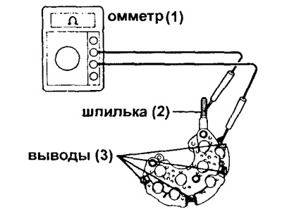
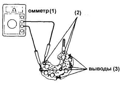
1. Check the positive valves.
A) Connect one lead of an ohmmeter (1) to positive (+) conclusion (hairpin) (2) rectifier block, and the other, in turn, to other conclusions (3).
b) Reverse the polarity of the ohmmeter leads and repeat the previous procedure.
V) Make sure that in the first case the ohmmeter shows the presence of conductivity, and in the second case - its absence.
Otherwise, replace the rectifier unit.
2. Check negative valves.
A) Connect one lead of an ohmmeter (1) to a negative conclusion (hairpin) (2) rectifier block, and the other, in turn, to other conclusions (3).
b) Reverse the polarity of the ohmmeter leads and repeat the previous procedure.
V) Make sure that in the first case the ohmmeter shows the presence of conductivity, and in the second case - its absence.
Otherwise, replace the rectifier unit.
Bearings
1. Check the front bearing. Make sure the bearing rotates smoothly without binding.
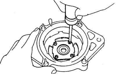
2. Replace bearing if necessary.
Loosen 4 screws, remove bearing holder and front bearing. Install a new bearing.
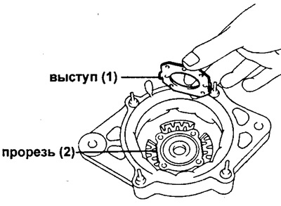
Align the mounting tabs (1) slotted bearing holder (2) in the cover of the generator (for models 55A, 60A, 70A). Tighten the screws securing the bearing holder.
3. Check the rear bearing, making sure it rotates smoothly without binding.
4. Replace rear bearing if necessary.
A) Using a suitable puller, remove the bearing from the rotor shaft.
Warning: Do not damage the generator fan.
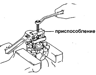
b) Using a suitable tool and a press, press in the new bearing and bearing cap.