
Generator parts (1980-87)
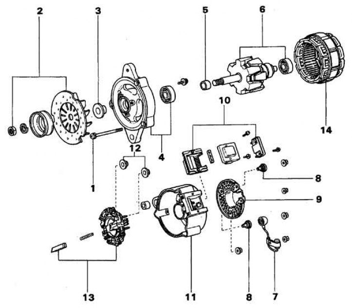
1. Coupling bolt; 2. Pulley and impeller; 3. Separating sleeve; 4. Front cover and bearing; 5. Ring; 6. Rotor and bearing; 7. Capacitor; 8, 12. Insulator; 9. Back cover; 10. Regulator; 11. Brush holder housing; 13. Brush holder and straightener; 14. Stator
Generator parts (1988-92)
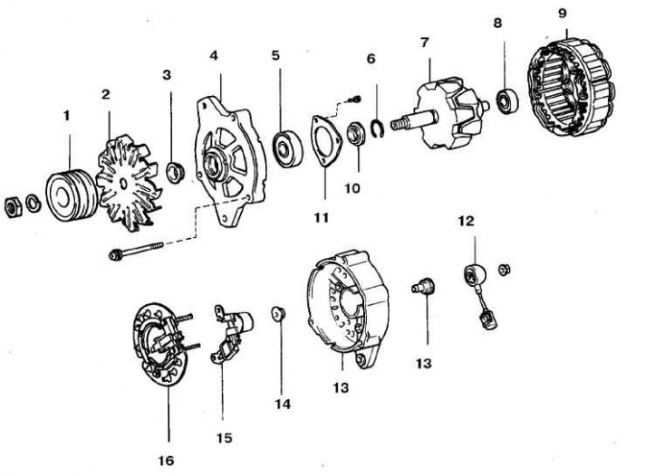
1. Cabinet and impeller; 2. Impeller; 3. Separating sleeve; 4. Front cover; 5, 7. Bearing; 6. Stator; 8. Rotor; 9. Retaining ring; 10. Distance strip; 11. Bearing cover; 12. Capacitor; 13. Rectifier housing; 14. Insulator; 15. Regulator; 16. Rectifier
Generator parts (since 1993)
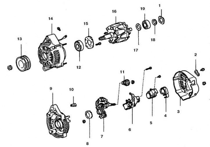
1. Thrust washer; 2. Rectifier plate; 3. Back cover; 4. Brush holder cover; 5. Brush holder; 6. Regulator; 7. Rectifier holder; 8. Seal; 9. Rectifier housing; 10. Insulator; 11. Terminal insulator; 12, 19. Bearing; 13. Skiff; 14. Stator; 15. Rear bearing cover; 16. Rotor; 17, 18. Bearing cap
Attention! The generators of the cars in question differ only in the layout of the voltage regulator.
Disassembly
1. Remove the generator.
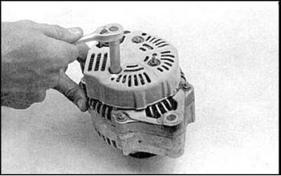 | 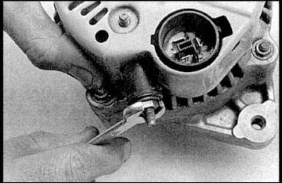 |
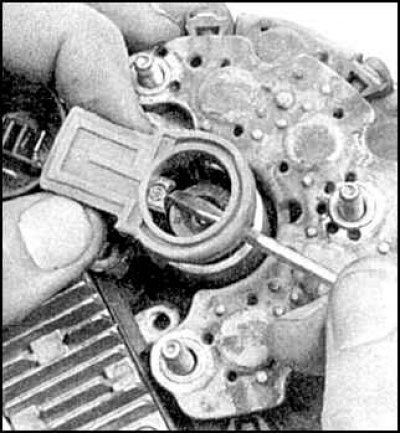
2. Loosen rear cover nuts (photo on the left), alternator output nut, remove grommet and rear cover (photo on the right).
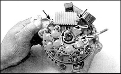
3. Unscrew the five screws securing the voltage regulator and brush holder (indicated by arrows).
4. Remove the voltage regulator.
5. Remove the brush holder. If you limit yourself to only replacing the voltage regulator, then do the work according to item 9, install a new regulator, assemble the generator and install on the engine. If the brushes will change, then be guided by the following paragraph of the description.
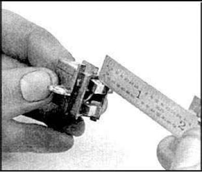
6. Measure the length of the protruding part of the brushes. If the brush length is less than the maximum allowable, replace the brush holder assembly with brushes. On some cars, only the brushes can be replaced by soldering them.
7. Make sure the brushes move freely in the brush holder.
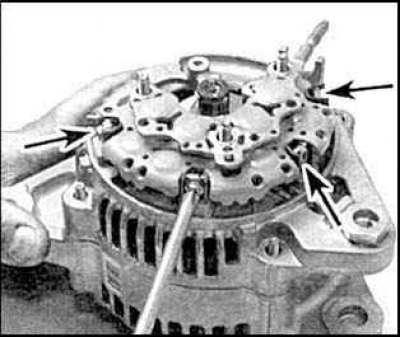
8. Remove the rectifier (rectifier mounting screws are indicated by arrows). Remove the four rubber buffers and the mud deflector.
9. Mark the relative orientation of the front and rear covers to facilitate assembly.
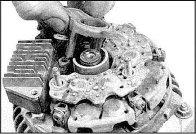
10. Loosen the pulley nut on the rotor and remove the pulley.
11. Unscrew the four nuts securing the front cover to the rear flange, disconnect the rear flange from the cover.
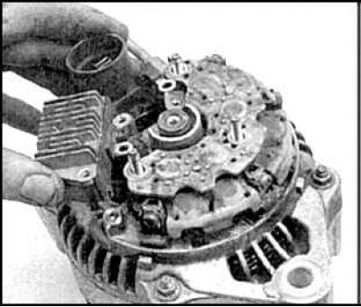
12. Remove the thrust washer and remove the rotor from the front cover.
Checking the condition of parts
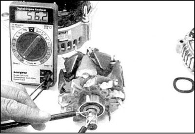 | 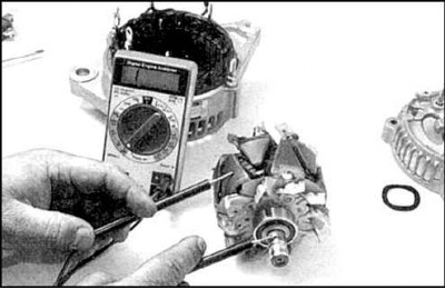 |
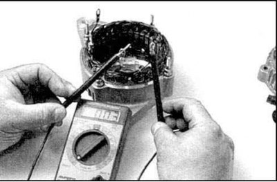
1. Check circuit resistance between two slip rings (photo on the right) which should be within 2-4 ohms. Check the circuit between the rotor shaft and the slip rings (photo on the left). The ohmmeter should show infinite resistance. If the results of both checks are unsatisfactory, or in case of increased wear of the rings, replace the rotor.
2. Check the resistance between the stator winding leads. If the resistance is high, or the ohmmeter shows an open, then the stator must be replaced. Check the short circuit of the stator windings on the case (core). If the ohmmeter shows a finite resistance between the stator terminals and the case, then the stator is faulty.
3. Check the positive and negative diodes of the rectifier bridge.
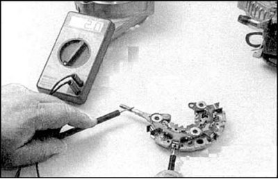 |  |
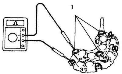
4. First, check the diodes of the positive branch of the rectifier bridge, for which the positive probe of the ohmmeter is attached to the output pin, and the negative probe to any of the diode outputs indicated in the illustration (photo on the left). Then swap the probes and touch the same pins (photo on the right).
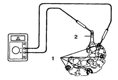
5. On the first connection, the ohmmeter should show a closed circuit, and on the other, an open circuit. Similarly, check the resistance between the other terminals. If at least one of the diodes fails the test, then the diode branch is considered faulty (1 - rectifier leads, 2 - positive lead).
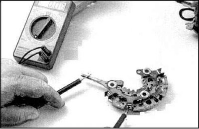
6. Now check the diodes of the negative branch of the rectifier bridge, for which the negative probe of the ohmmeter is attached to the negative terminal (1), and the positive probe to any of the rectifier terminals. Then swap the probes and touch the same pins. When first connected, the ohmmeter should indicate an open circuit, and on the other, a closed circuit. Similarly, check the resistance between the remaining terminals.
7. If at least one of the diodes fails the tests, then the diode branch is considered to be faulty.
Assembly
1. Assembly is carried out in the reverse order, subject to the following rules.
2. When installing the brush holder on the rotor, press the brushes out with a small screwdriver.
3. Screw in the screws securing the voltage regulator and brush holder.
4. Install the back cover and tighten the nuts.
5. Install the insulating sleeve of the pin, tighten the nut.
6. Install the generator.