
Removal and installation are carried out as follows:
- Raise the engine using the lifting cables and remove the rear engine mount.
- Unscrew and knock out the bolt from the crosspiece of the intermediate steering shaft on the gear.
- Also remove the coupling bolt from the hinge from the top side.
- Remove the intermediate shaft from the gear, move it to the side and then disengage from the top.
- Remove the cotter pins and locknuts of the steering rod joints and press out the hinge pins with a puller, as shown in Figure 225.
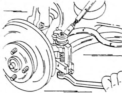
Pic. 225. Pressing out the steering rod ball joint
- Remove the middle beam under the engine (Pic. 226)
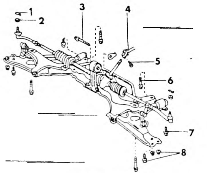
Pic. 226. The suspension transverse beam and wishbones are removed before removing the steering. When installing, ensure the specified tightening torques: 1. Cotter pin; 2. Nut 50 Nm; 3. Bolt. 80 Nm; 4. Steering intermediate shaft; 5. Bolt. 36 Nm; 6. Bolt. 140 Nm; 7. Bolt. 140 Nm; 8. Bolts and nuts 130 Nm.
- Loosen the clamp bolts. Please note that the rubber bushings of both struts and rubber steering mounts are not the same and should be folded separately. After this you can remove the steering. Figure 227 shows the fastening of steering parts.
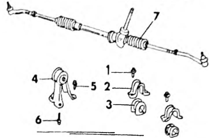
Pic. 227. Mechanical steering after removing the suspension cross member. 1. Bolt.60 Nm; 2. Mounting clamp; 3. Rubber support; 4. Bolt.60 Nm; 5. Bolt. 90 Nm; 7.Steering
Installing the steering control is done in the reverse order. Place both rubber mounts on the steering in their original position. The same applies to clamps. Straighten the steering and alternately tighten the 4 mounting clamp bolts to a tightening torque of 60 Nm. Install the wishbone by engaging the intermediate steering shaft. The front wheels should be in a straight position. Tighten the hinge bolts to a torque of 35 Nm. Install the suspension cross member, engine center beam, muffler pipe, etc., as described in chapter "Left shaft with automatic transmission". Install the cross bars onto the cross beam. The tightening torques are shown in Figures 201 and 226. Connect the steering rods, tighten the nuts to a torque of 50 Nm and secure them with new cotter pins.