
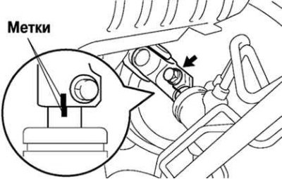
Pic. 5.26. Labels on the intermediate shaft and steering shaft
Mark the intermediate shaft and steering shaft (pic. 5.26).
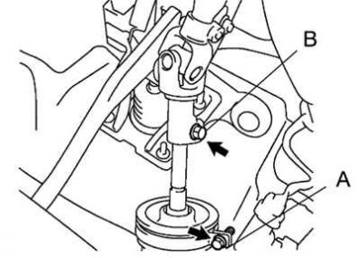
Pic. 5.27. Intermediate shaft mounting bolts
Remove bolt A. Remove bolt B and remove intermediate shaft assembly (pic. 5.27).
Tightening torque: 35 Nm.
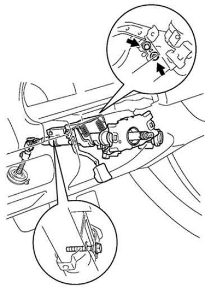
Pic. 5.28. Removing the steering column
Disconnect the connectors, unscrew the four fastening nuts and remove the steering column assembly (pic. 5.28).
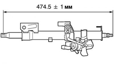
Pic. 5.29. Measuring the length of the drive shaft
Check the steering column for mechanical damage. Measure the length of the drive shaft (pic. 5.29).
Standard length: 474.5±1 mm.
If the length is not as specified, replace the steering column assembly.
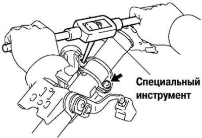
Pic. 5.30. Drilling taper head bolts
Using a special tool, drill out the cone head bolts and remove them from the bracket (pic. 5.30).
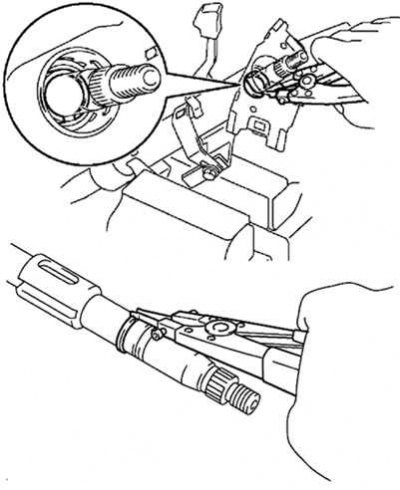
Pic. 5.31. Removal of spring rings of a conducted shaft
Using an expander, remove the spring rings of the driven control shaft (outer side and inner side) (pic. 5.31).
Remove the ignition lock bracket from the steering column tube. When installing the ignition lock, use new bolts with a conical head. Tighten them until the heads are cut off.