
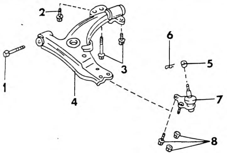
Pic. 197. Parts of the wishbone together with the suspension ball joint
In addition to the left drive with an automatic transmission installed:
- Remove the 3 bolts from the rear side of the wishbone.
- Remove the bolt from the outside of the front side of the control arm. To make it easier, grab the wishbone and move it in both directions, pulling out the bolt with pliers. Since the transverse arm is under tension, the bolt may jam.
- Pull out the wishbone. Figure 198 shows the mounting of the transverse arm from the front side (bolt and nut) and from the back (3 bolts).
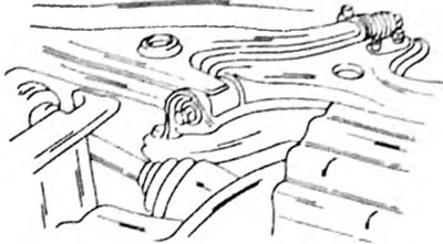
Pic. 198. The wishbone is attached at the front and rear in the manner indicated
Left shaft with automatic transmission installed
- Disconnect the steering intermediate shaft. See chapter for details "Steering".
- Remove the cotter pins and castle nuts on both steering ends and press the ball joints out of the steering arms using a suitable puller.
- Remove all panels under the front of the vehicle.
- Remove the 11 bolts and two nuts shown in Figure 199 that secure the middle beam to the body. The plugs must be removed to gain access to the bolts and nuts in the middle.
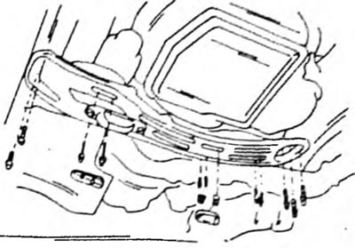
Pic. 199. To remove the beam, unscrew the indicated bolts and nuts from the car (11 bolts, 2 nuts). First remove the two rubber plugs
- Disconnect the muffler pipe from the exhaust manifold. Remove the gaskets. When installing, the gaskets must be replaced. Release the muffler pipe from the other end (if present, disconnect electrical wires), and remove the muffler pipe assembly.
- If equipped with power steering, unscrew the supply and return pipes. Wipe off any leaking liquid so as not to contaminate the work area.
- Unscrew the bolts and nuts on the underside of both transverse arms, indicated by arrows in Figure 200, and separate the ball joints from the transverse arms.
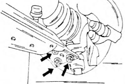
Pic. 200. The arrows indicate where the suspension joint is attached to the wishbone
- Unscrew the lower wishbones with the suspension cross member from the underbody of the vehicle. A roller jack must be placed under the cross beam before unscrewing. First remove the nuts and bolts from the rear engine mount and then the 6 cross member mounting bolts. Lower the cross member on the jack.
- Unscrew the lower nut of the stabilizer bar connecting rod on the left transverse arm and disconnect the rod.
- Remove the bolt from the front and rear of the control arm and remove the control arm from the cross member.