



Contents: Direct Drive Starter ↓ Starter with gearbox ↓
Figure 274 shows a typical direct drive starter installed on TOYOTA vehicles. There are differences between both starter designs. Both designs are described separately. The condition for disassembly is experience with starters.
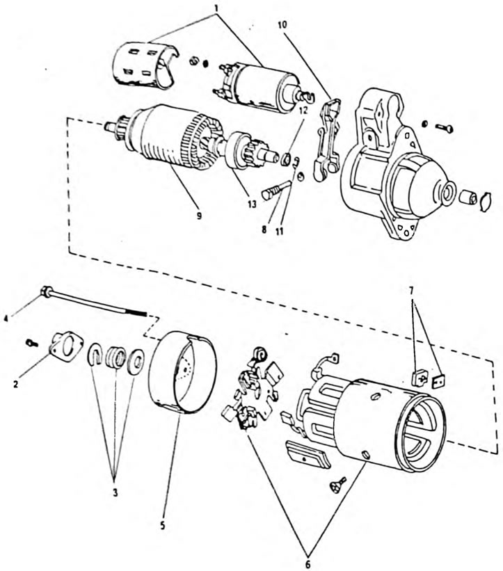
Fig. 274. Starter assembly drawing 1. Traction relay; 2. Lid; 3. Locking bracket. Spring and rubber washer; 4. Bolt; 5. Collector bearing shield; 6. Starter housing with brush holder.; 7. Metal and rubber inserts.; 8. Support finger of the engagement lever; 9. Anchor; 10. Power lever; 11. Support ring; 12. Thrust ring; 13. Overrunning clutch with drive gear
Direct Drive Starter
- Disconnect the wires from the traction relay terminals.
- Loosen the bolts and remove the cap (2).
- Unscrew the two relay mounting bolts and remove the traction relay.
- Before further disassembly and if a major overhaul is planned, the axial play of the anchor shaft should be checked. To do this, as shown in Figure 275, insert a feeler gauge between the washer and the spring. The gap should be between 0.05 and 0.60 mm. Record the measured gap, as it will be needed during assembly.
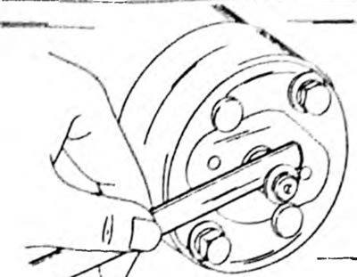
Fig. 275. Measuring the axial play of the armature shaft before disassembling the starter
- Unscrew the two tie bolts (4) from the rear side of the starter and remove the drive bearing shield together with the anchor from the starter housing.
- Remove the engagement lever (unscrew bolt "8") and pull the anchor out of the drive bearing shield. Note the way the lever is installed so that you can later assemble the parts in their original position.
- Remove the back cover.
- Remove the brushes from the holders and remove the brush holder (14).
- Hit the thrust ring at the end of the armature shaft with a chisel and remove the retaining ring underneath (Fig. 276). Clean the end of the shaft and remove the gears from the shaft.
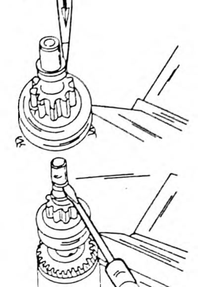
Fig. 276. Knocking off the flange ring with a chisel and removing the locking sleeve in the lower figure.
Starter with gearbox
Figure 277 shows this starter in a disassembled state.
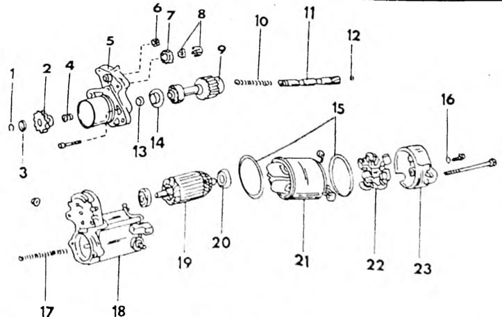
Fig. 277. Assembly drawing of a starter with a gearbox using a 1.6 l engine as an example. 1. Retaining ring; 2. Gear; 3. Thrust ring; 4. Starter spring; 5. Starter gear housing; 6. Intermediate gear; 7. Reduction gear; 8. Bearing; 9. Freewheel clutch; 10. Pressure spring; 11. Connecting shaft; 12. Steel ball; 13. Spring cup; 14. Bearing thrust; 15. Sealing ring; 16. Sealing ring; 17. Return spring; 18. Traction relay; 19. Anchor; 20. Rear bearing; 21. Starter housing with stator windings; 22. Brush holder; 23. Lid.
Disassembly is carried out as follows:
- Unscrew the nut and remove the wire from the traction relay terminal.
- Unscrew the two bolts and pull out the starter housing together with the anchor. The 1.4 kW starter has a sealing ring.
- Loosen the two screws at the end of the starter gear and remove the gear housing with the freewheel clutch, return spring, bearing and intermediate gear of the gearbox. The 1.4 kW starter has an additional gear.
- There is a small coupling ball on the inside of the coupling shaft. A magnet can be used to remove the ball. Otherwise, the ball can be shaken out.
- Remove the cover from the other end of the starter, which is secured with two bolts. The 1.4 kW starter has a sealing ring.
- Use a screwdriver to separate the brush springs from the brushes and pull the brushes out of the holders. Disconnect the four brushes and unscrew the brush holder.
- Remove the anchor from the starter housing.