
Brush unit
Brushes must be longer than 10.0 mm. Check whether the brushes move easily in their guides by inserting them and lightly pulling the current guides to move them in both directions. If necessary, wipe the brushes with a rag soaked in gasoline or treat them with a thin file. If necessary, replace the brushes.
Anchor and manifold
The collector must be smooth over the entire surface, on which there should be no scoring or carbon deposits. Wipe the commutator with a rag soaked in gasoline while turning the armature, as shown in Figure 278. If this is not successful, the commutator can be treated with a piece of sandpaper, but do not use sandpaper for this. To bore a badly worn manifold, you can place it in a lathe and remove a layer of metal at high speeds. Do not remove more layer than necessary. In this case, the final diameter should not be less than 27.0 mm on a starter with direct drive and 29.0 mm on a starter with a gearbox. The collector is measured at the location shown in Figure 279.
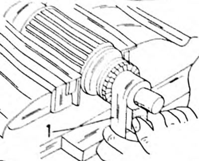
Pic. 278. Clean the collector with a strip of sandpaper (1) To strip around the entire circumference, clamp the anchor in a vice in different places
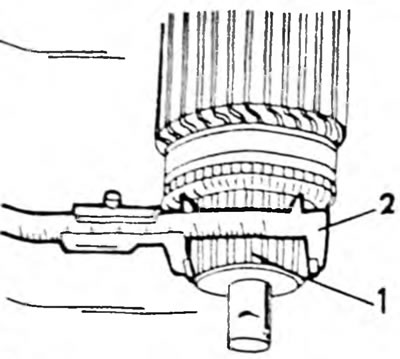
Pic. 279. Measuring the diameter of the collector (1) caliper (2)
Finally, use a hacksaw to saw through the lamella spaces between the collector segments to a depth of 0.5-0.8 mm. After this, polish the commutator with fine sandpaper until a shiny layer is obtained. Sawing of lamella spaces between collector segments is carried out if the depth is less than 2.0 mm. The most common malfunctions are caused by short circuits in the armature. A sign is burnt coils of the collector. On a starter with direct drive, check the armature shaft play in the bushings by measuring the shaft diameter and the inner diameter of the bushing and calculating the difference between these values. If it exceeds 0.20 mm, the bushings should be replaced. To check the armature winding, an armature test device, the so-called buzzer, is required. If there is no device, you can check the anchor by temporarily installing a new anchor. Do not attempt to straighten a bent armature shaft or machine an armature core.
Stator windings
The stator windings can best be checked using an ammeter, which is connected to the winding terminal and ground with the battery connected in between (Pic. 280). If there are indications, the winding is shorted to ground. For the second check, connect an ammeter to both brushes (Pic. 281). If there is no reading, there is an open circuit. In both cases, replace the starter housing or windings. The contact bolts are unscrewed with an impact screwdriver, as they are tightly tightened. On a starter with a gearbox, the entire housing is replaced.
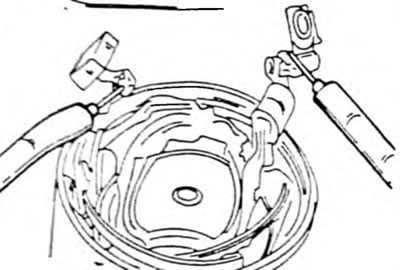
Pic. 280. Monitoring of field windings for contact with ground
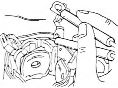
Pic. 281. Monitoring of field windings for open circuit
Bearings
Bearings that are so broken that there is lateral play in the armature shaft must be replaced. | To do this, it is best to measure the outer diameter of the shaft and the inner diameter of the bushings. If the difference exceeds 0.20 mm, the old bushings should be pressed out, new ones should be pressed in and the bushings should be ground in until the armature shaft has a play of 0.035-0.08 mm.
Starter drive
Check the condition of the drive gear teeth. The gear should move easily along the threaded part of the armature shaft. The freewheel should only rotate in one direction, locking in the opposite direction. If necessary, replace the entire drive, but count the drive gear teeth before ordering parts.
If the drive gear is replaced due to tooth damage, be sure to check the ring gear.
Traction relay
The traction relay cannot be repaired. To check the winding of the traction relay, connect a 12 V battery to the terminals "WITH" And "50". There should be a current reading and the drive gear should pop out. This check confirms the serviceability of the traction winding. To control the holding winding, connect as indicated in both figures and disconnect the negative wire from the terminal "WITH". The drive gear must not change its position. If it jumps back, the traction belt should be replaced. Figure 282 shows the traction relay terminals of a conventional starter, and Figure 283 shows a starter with a gearbox.
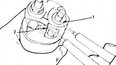
Pic. 282. Checking the traction relay with an ohmmeter (direct drive starter) 1. Terminal "WITH"; 2. Terminal "50"

Pic. 283. Checking the starter traction relay with gearbox1. Terminal "WITH"; 2. Terminal "50"
The third check should be carried out to monitor the return of the drive gear. To do this, disconnect the negative wire from the housing (pic. 283). The gear should immediately jump inside. If this does not happen, replace the traction relay.