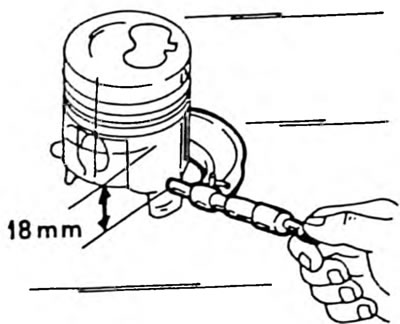
To measure the cylinders, a cylindrical dial indicator (Fig. 89) is required, which can be used to measure in the middle and at the bottom of the cylinder. If the dial indicator is missing, the following work cannot be performed. The cylinders must be measured in the longitudinal and transverse directions. In addition, measurements must be taken 15 mm from the upper edge, 15 mm from the lower edge and in the middle. A total of 6 measurements must be taken. Record all measurement results and compare with the data given in the tables of dimensions and adjustments. It should be noted that all cylinders must be bored, even if the dimensions of only one cylinder differ from the required ones. A deviation of 0.20 mm from the required value means that the cylinder must be bored. Pistons have only one repair size. The final cylinder size is determined by measuring the piston in accordance with the data in Fig. 314, i.e. 18.0 mm from the piston pin. Measurements are taken under the lowest groove of the piston. A piston clearance of 0.04-0.06 mm should be added to the measured value. In addition, an allowance of 0.02 mm should be taken into account for final honing if the cylinders are to be bored. To check the piston clearance, measure the cylinder diameters and piston diameters as described above and calculate the difference for each cylinder. If the result exceeds 0.20 mm, the cylinders should be bored to install oversized pistons (there is only one size available), because the play has reached the wear limit.
Fig. 314. Measuring the piston diameter on a diesel engine.