
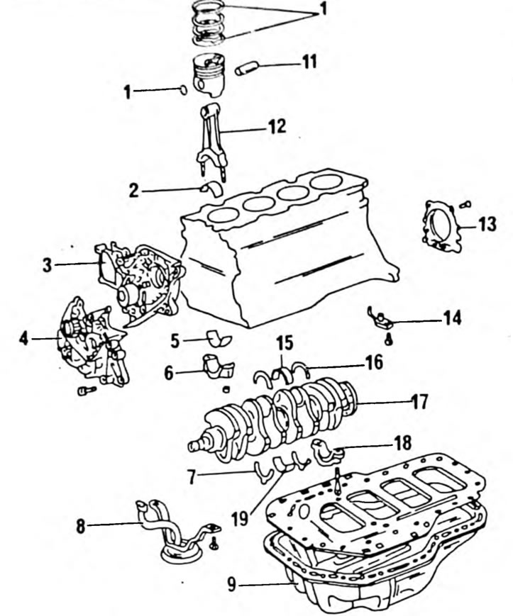
Pic. 313. Installation drawing of the crank mechanism of a diesel engine. 1. Retaining ring; 2. Connecting rod bearing shell; 3. Water pump; 4 Oil pump; 5. Connecting rod bearing shell; 6. Connecting rod bearing cover; 7. Lower half ring; 8. Oil intake mesh; 9. Oil pan; 10. Piston rings; 11. Piston pin; 12. Connecting rod; 13. Rear oil seal flange; 14. Oil injection nozzle; 15. Crankshaft main bearing shell; 16. Crankshaft; 17. Main bearing cover; 18. Crankshaft main bearing shell
To separate the pistons from the connecting rods, the piston pin circlips must be removed. Then place the plunger in hot water (not less than 80°С) and knock it out using a suitable drift and hammer. Remove the piston rings using piston ring pliers. Checking the pistons and connecting rods is carried out in the same way as is done on gasoline engines, but taking into account the values given in the tables of sizes and adjustments. The connecting rod bearing shells are selected in accordance with the tolerance values. The bearing shells are marked with the numbers 1, 2 or 3 and the same number is stamped on the outside of the connecting rod bearing caps. Be sure to ensure that both markings match.