
- Crank the engine until the piston of the first cylinder is in the TDC position. In this case, the mark on the pulley should coincide with the pin on the oil pump housing.
- Check that the valve tappets of the first cylinder have a slight play, and the valve tappets of the fourth cylinder are seated tightly. If this is not the case, turn the engine one more revolution.
- Measure the valve clearances in accordance with Figure 310 using feeler gauges inserted between the pusher and the cam surface. Intake clearances (E) and graduations (A) valves are not the same on all engines and are listed in tables of sizes and adjustments.
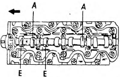
Pic. 310. Sequence of valve clearance adjustment when installing the first cylinder to the TDC position. E = intake camshaft; A = exhaust camshaft
- Turn the engine one full turn and measure the clearances indicated in Figure 311. A sign of correct adjustment is when the end of the feeler gauge is inserted, and then, under light pressure, the feeler gauge bends and goes inward. To adjust the valve clearances, the shims on the top side of the pushrods must be replaced, but a special tool is required to remove and install the shims. To do this, rotate the crankshaft until the corresponding cam is installed with the point up and using the special tool shown in Figure 312, or otherwise press the pusher inward so that you can grab and pull out the adjusting washer with a small screwdriver and a magnet. Before pressing the pusher, it should be turned so that the notch on the top side faces the spark plugs. Both pushers are pressed simultaneously, that is, it is necessary to ensure that both pushers are pressed by the foot of the device.
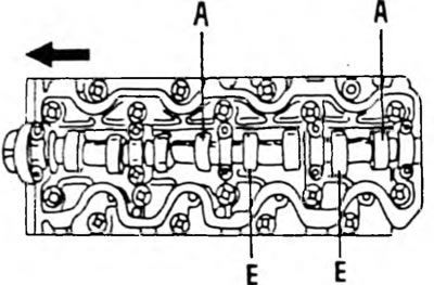
Pic. 311. Adjust the canceled valve clearances when installing the piston of the fourth cylinder to the TDC position. E = intake camshaft; A = exhaust camshaft
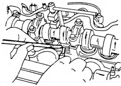
Pic. 312. Using a special device to press the pushers into their holes. To remove the adjusting washers, use a screwdriver and a magnet.
- The shim to be installed can be calculated using the following formula:
- Measure the removed washer with a micrometer (Pic. 85) and write down the result.
- Calculate the thickness of the new washer to ensure the required valve clearance. The following formula is used:
Intake valves:
N = T + (A - 0.25 mm)
Exhaust valves:
N = T + (A - 0.30 mm), Where "T" - thickness of the removed washer, "A" - measured valve clearance and "N" - thickness of the new washer to be installed.
- Select a washer that is closest in thickness to the required gap. There is a range of 25 sizes of washers ranging in thickness from 2.2mm to 3.4mm at 0.05mm intervals.
- To install the adjusting washer, press the pusher inward again and insert the washer.
- Measure the valve clearance as described above.
- Adjust the clearances of the remaining valves.
- Under no circumstances should the adjusting washer fall into the engine. To avoid this, use a small screwdriver and a magnet, as shown in Figure 312. The washer can then be pulled out to the side and "captured" magnet