
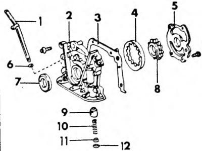
Pic. 113. Installation drawing of a tin pump for a 1.6 liter engine. 1. Oil dipstick; 2. Oil pump housing; 3. Housing gasket; 4. Driven rotor; 5. Oil pump housing cover; 6. O-ring; 7. Oil seal; 8 Drive rotor; 9. Pressure reducing valve; 10. Spring; 11. Spring stop; 12. Retaining ring
Removing and installing the oil pump
- To remove the oil pump, remove the oil pan and the oil receiver screen.
- Drain the engine oil. If the oil was added recently, collect the leaking oil in a container for refilling.
- Remove the oil pan (Chapter 3.1).
- Unscrew the two bolts securing the oil intake pipe from the inside of the crankcase and unscrew the fastenings of both support rods. Remove the oil receiver screen with the tube. Remove the oil deflector screen.
- Remove the toothed belt as described in the relevant chapter.
- Remove the oil dipstick and unscrew the guide tube.
- Unscrew the pump mounting bolts on the front side of the cylinder block. The pump is located in the location shown in Figure 114.
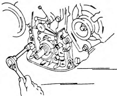
Pic. 114. Removing the pump housing from the front side of the engine.
- Remove the pump and remove the gasket. If the pump is sitting very firmly, you can gently tap the pump housing from the inside of the crankcase with a plastic hammer.
- Install the pump in the reverse order. Be sure to replace the pump gasket. Install and tension the toothed belt in accordance with the instructions in the relevant chapter. Adjust the tension of the alternator V-belt and water pump according to the instructions chapter 4.3.2.
- After installing the oil pan, fill the engine with oil as described in chapter 3.1.
Oil pump overhaul
- Unscrew the oil pump cover from the inside of the front of the housing.
- Remove the inner and outer gears from the housing. Before removing the gear, mark the direction of rotation on the rear side with a felt-tip pen.
- Remove the retaining ring from the front of the housing and remove the pressure reducing valve parts. The position of the individual parts can be seen from Figure 113.
Clean all parts and replace if necessary. If there is wear on the front part of the housing or cover on the working surfaces, replace the parts; otherwise, carefully pry up the oil seal with a screwdriver. Check the piston bore of the pressure reducing valve for wear and absence of scoring.
Check for broken teeth on the rotor. The rotors must be replaced as a set. Insert the rotor into the hole, as shown in Figure 115, and use a feeler gauge to measure the gap between the outer side of the outer rotor and the pump hole (on the left in the picture). The gap should not exceed 0.2 mm. For the next check, insert a feeler gauge between the tip of the outer rotor and the tip of the inner rotor (medium rice). The gap should not exceed 0.35 mm.
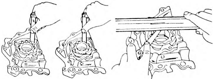
Pic. 115. Oil pump clearance control (see text)
Place a ruler on the surface of the rotor and housing (right fig.) and measure the gap between the linear and rotors with a feeler gauge. The gap should not exceed 0.10 mm. If the measurements obtained results exceeding the specified values, replace the rotors as a set. Reassembling the oil pump is done in the reverse order. Insert the outer rotor with the marked side facing out. Before installing the cover, fill the pump hole with oil. Insert the pressure reducing valve parts and secure with the retaining ring.