
Removing
Place the car on a lift.
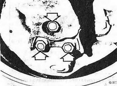
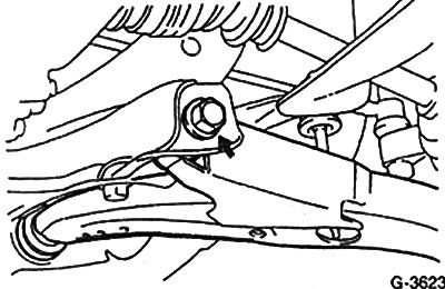
Remove one bolt and two nuts connecting the ball joint to the control arm.
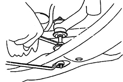
Disconnect the control arm stabilizer bar support.
Cars up to 4/87 of release
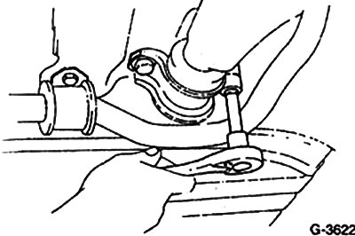
Vehicles since 5/87
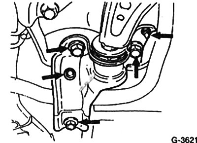
Loosen the bolts and nuts at the rear control arm bushing.
Disconnect the front control arm bushing and remove the control arm.
Attention: Cars from 5/87 with automatic transmission: The left suspension arm cannot be removed separately. The axle beam must be removed as a set. Dismantling is carried out as follows:
Disconnect the left and right control arms at the ball joints.
Disconnect the rear left and right lever holders.
Remove stabilizer.
Place a workshop jack under the cross beam so that it does not fall after removing the fasteners. It is recommended to perform this operation with the help of an assistant.
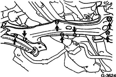
Unscrew 6 bolts and two nuts and remove the cross member together with the control arms.
Detach the arms from the cross member.
Checking and replacing the rear silent block.
Check the control arm bushing for porosity and damage.
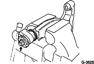
To give a nut, to remove a lock ring and the plug.
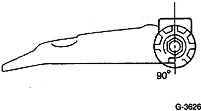
Install the new bushing and circlip with the bushing vertical to the lever.
Tighten the nut: for vehicles up to 4/87 to 85 Nm, for vehicles from 5/87 to 135 Nm.
Installation
Install the lever on the beam. Screw on the bolts and nuts without tightening them.
Left suspension arm for vehicles from 5/87 with automatic transmission: Install the beam with the arms attached to it on the underbody. Tighten the mounting bolts, see drawing G-3624.
Install the stabilizer without tightening its mounting bolts.
Tighten 1 bolt and 2 nuts securing the control arm to the steering knuckle. Tightening forces: for cars up to 4/87 of release - 65 Nm; for cars from 5/87 of release - 140 Nm.
Take the car off the lift.
Push the car several times by hand to settle the suspension.
Tighten stabilizer mounting bolts.
Vehicles up to 4/87: Tighten the front transverse arm mounting bolts to 115 Nm, the rear mounting to 90 Nm.
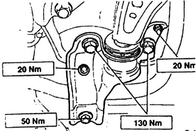
Cars from 5/87 of release: Tighten bolts of fastening of a forward support of the cross-section lever with a force of 235 Nm, a back holder on a cross beam with the force specified in fig. G-3628.
Have the geometric parameters of the front suspension measured in a specialized workshop. Perform the operation as soon as possible.