
Arrangement of knots of system of fixing of the selector
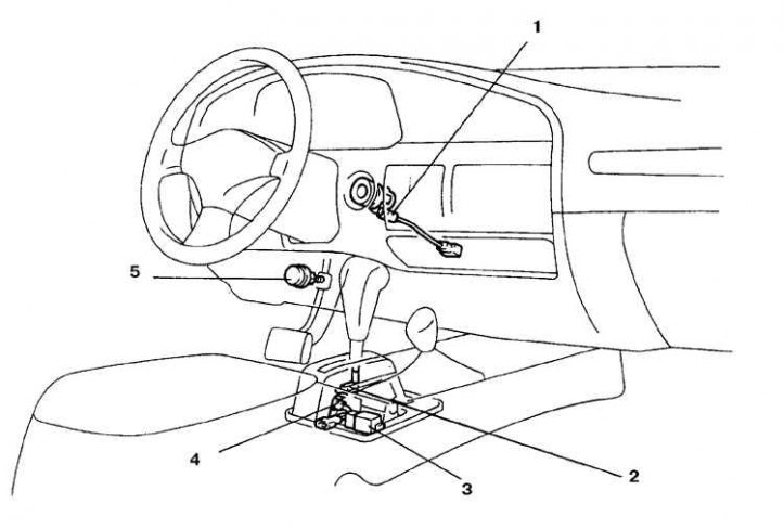
1. Key interlock solenoid; 2. Selector lock solenoid; 3. Selector control unit; 4. Selector lock switch; 5. Stop signal switch
The system ensures that the selector is locked in the Park or Neutral positions with the brake pedal depressed. All maintenance work on the system, except for those described below, is carried out in a car service.
Examination
1. To access the components of the system, the floor section must be removed.
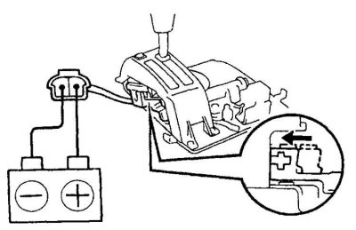
2. Disconnect the connector and apply battery voltage to the selector lock solenoid terminals. If there is no characteristic click, replace the solenoid.
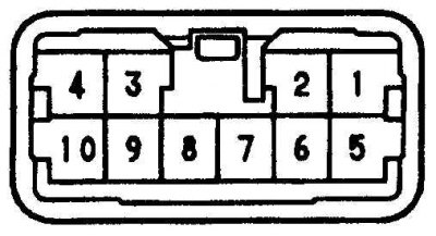 | 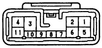 |
3. Disconnect the key interlock solenoid connector and check the resistance between pins 1 and 5 (pic. on the left - for a / m 1991-95), between terminals 7 and 8 (pic. right - for vehicles from 1995), which should be 12–17 ohms.
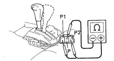
4. Disconnect the connector from the selector lock switch and check the resistance between the indicated terminals.
5. In the Park selector position, there must be a circuit between terminals P and P1.
6. In the position of the selector Park and the button pressed, there must be a circuit between the terminals P and P1 and P and P2.
7. In the remaining positions of the selector R, N, D, 2 and L, there must be a circuit between the terminals P and P2.
8. If the results of the checks are different, then replace the defective parts and repeat the checks.