
Note: work only on a cold engine.
1. (Engine 2L-T)
Remove the air filter.
2. (Except 2L-T engine)
Remove the intake duct.
3. (Engine 1KZ-T) Removing the intake duct.
A) Disconnect the vacuum valve connector and two vacuum hoses.
b) Disconnect the two wire harness clips.
V) Turn away nuts of fastening, remove sealing washers.
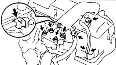
G) Disconnect the two crankcase ventilation hoses.
d) Remove the air duct clamp, dismantle the air duct and gasket.
4. Remove the protective cover of the cylinder head (if installed).
5. Remove the valve cover of the cylinder head.
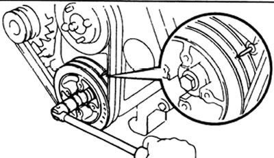
6. Set the piston of the first cylinder to TDC.
A) By turning the crankshaft pulley clockwise, align its groove with the benchmark.
b) The cams of the first cylinder should be directed upwards, the fourth downwards.
V) If the specified condition is not met, then turn the crankshaft one revolution (360°) and align the marks as above.
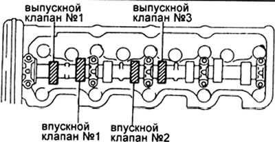
7. Adjustment of the thermal gap.
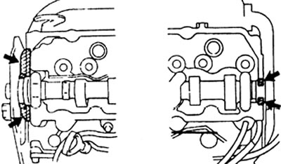
A) Check only the valves marked in the figure.
- Measure the clearance between the valve lifter and the camshaft using a feeler gauge.
- Record valve clearance measurements that are out of specification. These records will be used to determine the thickness of the shim.
gaps (cold engine):
Series L:
- Inlet valve 0.20 - 0.30 mm
- Exhaust valve 0.40 - 0.50 mm
KZ Series:
- Inlet valve 0.20 - 0.30 mm
- Exhaust valve 0.25 - 0.35 mm
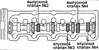
b) Rotate the crankshaft one turn (360°) and align the marks as above.
V) Measure the clearances of the valves marked in the figure.
G) Remove the adjusting washer.
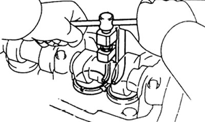
- Rotate the crankshaft until the cam lobe points up.
- Using the special tool, press the valve lifter down.
Note: Before pushing the valve lifter, position the notch on the tappet on the exhaust manifold side.
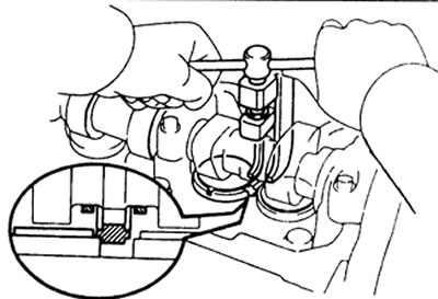
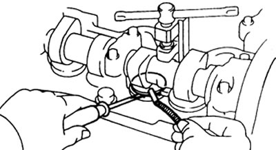
- Using a small screwdriver and a magnet, remove the shim.
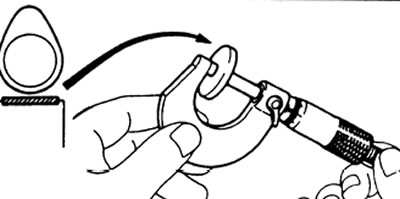
d) Measure the thickness of the washer that was removed. Determine the size of the new shim using the formula:
for inlet valve
N=7 + (A - 0.25 mm)
for exhaust valve
L-series: N=T+ (A - 0.45 mm)
KZ series: N=T+ (A - 0.30 mm)
where: T is the thickness of the previously used washer,
A is the measured valve clearance.
N is the thickness of the new washer.
Select a new washer that is closest to the calculated thickness.
Note: Washers are available in seventeen sizes in 0.05 mm increments ranging from 2.50 mm to 3.30 mm.
e) Install a new shim on the valve lifter.
and) Recheck the clearance.
8. Install the protective cover of the cylinder head (if installed).
9. (Except KZ) Reinstall the cylinder head valve cover.
10. (2L-T) Install the air filter.
11. (1KZ-T) Valve cover installation.
A) Remove any remaining old sealant.
b) Apply sealant to the cylinder head at the locations shown in the illustration.
V) Install the valve cover by tightening the 10 bolts and 2 nuts.
Tightening torque: 9 N.m
12. (All engines) Install the intake duct.
13. (1KZ-T) Installing the intake duct.
A) Install a new gasket on the intake manifold.
b) Install the air duct, secure it with a clamp. Make sure that the latch of the clamp enters the slot.
V) Connect the two crankcase ventilation hoses.
G) Install the sealing washers, tighten the 4th fastening nuts to 12 Nm.
d) Install the two wire harness clips.
e) Connect the vacuum valve connector and two vacuum hoses.