
Hang the caliper without disassembling it, and securely fasten it with wire. Check if the brake hose is tight.
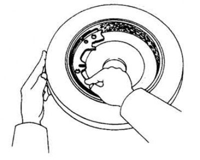
Release the parking brake lever (or pedal) and remove the rear brake disc.
Disassembly
Note. If the brake disc is difficult to remove, turn the adjusting gear until the brake disc turns easily (pic. 6.62).
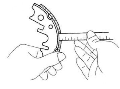
Pic. 6.63. Measuring the inner diameter of the brake drum
Measure the inner diameter of the brake drum (pic. 6.63).
If the drum has scratches, mechanical damage or increased wear, then it can be bored to the maximum allowable inner diameter
- Standard Diameter: 170mm
- Maximum allowable: 171 mm
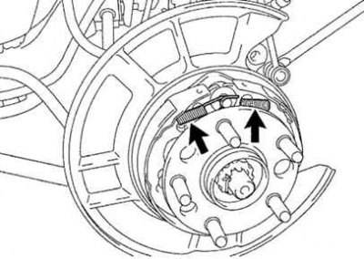
Pic. 6.64. Releasing the tension springs
Release the parking brake shoe return springs (pic. 6.64).
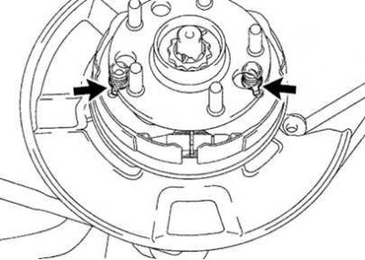
Pic. 6.65. Removing the parking brake pad adjusting screws
Remove parking brake pad adjustment screws (pic. 6.65.)
Remove the spacer plate along with the spring.
Remove the retainer spring, spring seats and retainer.
Disconnect the return spring and remove the front shoe.
Pull back the rear block.
Remove the return spring from the rear shoe.
Remove the retainer spring, spring seats and retainer.
Disconnect the parking brake cable from the parking brake lever.
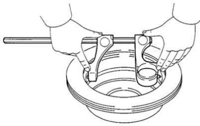
Pic. 6.66. Removing the parking brake lever
Remove the lock washer and parking brake lever (pic. 6.66).
Examination
Check the removed parts for wear, rust or damage.
Pic. 6.67. Measuring the thickness of brake pads
Measure the thickness of the brake pads (pic. 6.67).
- Standard Thickness: 2.0mm
- Minimum allowable: 1.0 mm
If the thickness of the pads is less than the minimum or they have uneven wear, replace the brake pads.
Note. If even one brake pad needs to be replaced, the entire set must be replaced.
Pic. 6.68. Checking the tightness of the brake pads to the brake drum
Check the tightness of the brake shoe lining to the drum (pic. 6.68).
If the contact between the working surfaces is poor, either grind the pads or replace the brake pads.
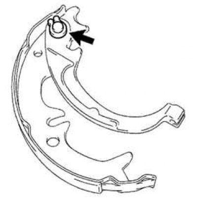
Pic. 6.69. Measuring the gap between the brake shoe and the parking brake lever
Using a feeler gauge, measure the clearance between the brake shoe and the parking brake lever (pic. 6.69).
Maximum allowable clearance: 0.35 mm.
If the gap does not meet specifications, select the correct thickness of the shim according to the data in the table.
Assembly
Reassemble in the reverse order of disassembly.
Apply high temperature grease to the parts indicated by the arrow in the assembly drawing.
Adjust parking brake pad clearance.
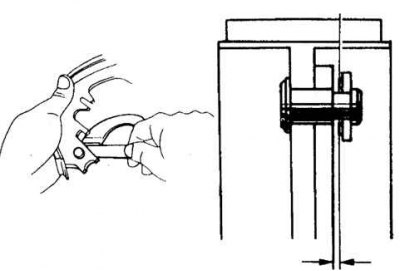
Temporarily install the wheel nuts and remove the plug.
Turn the adjuster to move the pads apart until they block the disc.
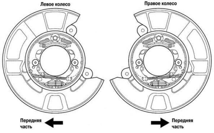
Pic. 6.70. Checking the correct installation of the brake discs
Check that all components are installed correctly (pic. 6.70).
While driving the vehicle at low speed on a dry, clean and level road, pull the parking brake lever so that the shoes are pressed against the drum. Make sure the pads are worn.
Check and adjust the travel of the parking brake lever.