



Contents: Valve springs ↓ Valve guides ↓ Valve seats ↓ Valves ↓ Cylinder head ↓ Valve seats ↓ Camshafts ↓ Toothed belt and gears ↓ Valve lifters ↓
Check all cylinder head parts for wear. Clean cylinder head surfaces (to remove the remains of the old seal, use a scraper without scratching the cylinder head material). Checks and controls shall be carried out in accordance with the following instructions.
Valve springs
A spring tester should be used to check the valve springs. If one is not available, a used spring can be compared with a new spring. To do this, clamp both springs, one behind the other, together in a vice and slowly tighten the vice. If both springs compress to the same value, this is a sign that they have approximately the same tension. But if the old spring compresses significantly more than the new one, then this is fatigue and the springs must be replaced as a set.
The length of the spring in a free state can be measured with a caliper, as shown in Figure 302. Place the springs one by one on a smooth surface (glass plate) so that the closed coil is on the lower side. Place a steel angle next to the spring. Measure the gap between the springs and the angle at the top (Fig. 46). The permissible size depends on the engine type. If the tolerance is exceeded, the spring is skewed.
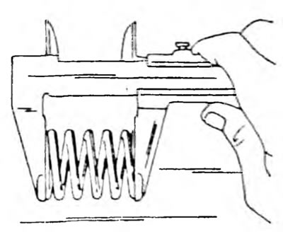
Fig. 302. Measuring the length of the valve spring with a caliper
Valve guides
Clean the guides by pulling a rag soaked in gasoline through the guides. It is better to clean the valve stems with a rotating wire brush inserted into the chuck of an electric drill and holding the valve stem next to it. Insert the valves into the holes one by one. To check the clearances of the valve stems in the holes, you need to have a dial indicator and a caliper. The check has already been described for gasoline engines, but on a diesel engine, the inner diameter of the guide bushings should be between 8.01 and 8.03 mm. The diameter of the valve stem is 7.975-7.990 mm for the inlet valves and 7.960-7.975 mm for the exhaust valves
Subtract the valve stem diameter from the inside diameter of the guide bushings. The result is the valve stem clearance in the bores, which should not exceed 0.10 mm for intake valves and 0.12 mm for exhaust valves.
Before installing the guide bushing, the general condition of the cylinder head is checked. Cylinder heads with small cracks between the valve seats or between the valve seat and the first thread of the spark plug hole can be reinstalled and reworked, provided that the cracks are no wider than 0.5 mm. Also check for skew of the cylinder head surface, which will be described below.
To replace the guide bushing, the old bushing must be knocked out with a punch from the top of the cylinder head. Before knocking out the guides, follow these instructions:
- Use a depth gauge or measuring ruler to measure how much the guide bushing protrudes above the top surface of the cylinder head.
- Heat the cylinder head to 80-100°C and knock out the old guide bushing from the top side towards the combustion chamber. The drift must have a groove at the end that matches the inner diameter of the guide bushing. Measure the inner diameter of the receiving hole in the cylinder head using a dial indicator. If the size is between 13.000 mm -13.027 mm, a guide bushing with a nominal outside diameter can be installed. If the diameter exceeds 13.027 mm, a guide bushing with an increased outside diameter must be installed. This means that the receiving holes for the guide bushings must be bored in the workshop. Do not try to simply hammer bushings with an increased outside diameter into the holes. If you have experience working with a reamer, you can ream the holes to a diameter of 13.050 - 13.077 mm to install oversized guide bushings. If the valve guides are replaced, the valves are also replaced and the valve seats must be lapped. Clean the inside surfaces of the receiving holes. Lubricate the new guides and drive them from the camshaft side into the cylinder head heated to 90°C so that the upper end protrudes above the upper surface of the cylinder head by the size measured before removing the old guides.
- After pressing, reamer the valve guides with an 8 mm reamer. The inlet valves should have a clearance of 0.02-0.055 mm; the exhaust valves must have a clearance of 0.035 - 0.070 mm.
- After replacing the valve guides, the valve seats must be milled. If the seats can no longer be machined, there is no point in replacing the guides.
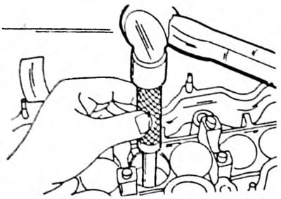
Fig. 303. Clogging of the valve guide bushing
Valve seats
Check the valve seats (see fig. 304) for wear and cavities. Minor signs of wear can be removed with a 45° cutter. However, if the seat is already heavily worn, the valve seats must be re-milled. The specified angles are shown in Figure 304. However, a correction angle must be provided to correct the valve seat chamfer height, i.e. a 30° cutter must be used (intake valves) or 60° (exhaust valves). As already mentioned, valve seats can be milled clean if new valve guides are installed. First, mill a 45° angle and then lightly mill the upper and lower edges of the seat with a 30 and 60 or 75° cutter to reduce the width of the seat chamfer and bring it to the middle. The width of the working seat chamfer should be 1.2-1.6 mm for intake valves and 1.6-2.0 for exhaust valves. Finish milling as soon as the seat chamfer has a width inside the tolerance. The finished seats must be lapped. To do this, apply grinding paste to the surface of the valve seat and insert the valve into the corresponding seat. Install a suction cup on the valve and turn the valve in different directions (see also fig. 52). After lapping, thoroughly clean all parts from paste and dirt and check the valve seat at the valve plate and the seat chamfer. The continuous matte ring characterizes the width of the valve seat chamfer and should be visible on both parts. Apply a few lines with a pencil on the "ring" on the valve plate. The lines should be applied in a circle at a distance of 1 mm. After this, carefully lower the valve into the guide sleeve and seat and turn the valve 90° with some pressure on the valve (use a suction cup for this). Remove the valve again and check whether the pencil marks have been removed from the chamfer. If the valve seat chamfer width is within the specified tolerances, the head can be reinstalled. Otherwise, machine the valve seats or, in the worst case, replace the head.
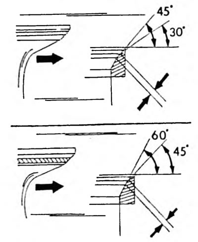
Fig. 304. Valve seats. The upper figure shows the seats of the intake valves, the lower figure shows the seats of the exhaust valves. The width of the working chamfer of the valve seat is measured between both arrows.
Valves
The description of the petrol engine valves also applies to the diesel engine valves. The valve plate edge size shown in Figure 53 should be 0.9 mm for the inlet valves and 1.0 mm for the outlet valves. Otherwise, new valves should be installed. The valves are measured in accordance with the table of dimensions and adjustments.
Cylinder head
Clean the contact surfaces of the cylinder head and cylinder block and check the cylinder head surface for distortion. To do this, place a measuring ruler on the head (Fig. 54) and use a set of feeler gauges to determine the clearance along, across and diagonally across the cylinder head surface. If it is possible to insert a feeler gauge larger than 0.20 mm, the cylinder head must be replaced. The same check should be carried out for the surface mating with the manifold. Here, too, a clearance of 0.20 mm is acceptable.
Valve seats
The valve seats in the cylinder head can be replaced. The old seats are knocked out from the top of the cylinder head into the combustion chamber. A compensation washer can be installed under the seat. New seats should be hammered in with a plastic hammer. The pin on the side of the seat and the notch in the cylinder head should be in line. After installation, check how much the seats protrude above the contact surface of the cylinder head. To do this, install a dial indicator on a suitable stand on a well-cleaned cylinder head and place the measuring probe on the surface of the cylinder head at the first seat to be measured. Set the indicator scale to zero. Now move the measuring probe to the edge of the seat. The difference in readings should be from -0.03 mm to +0.03 mm. If this is not the case, remove the seat again and place a compensation washer under it. There are a number of washers with a thickness of 0.05 to 0.10 mm, i.e. it is easy to select the right washer based on the measurement result. Hammer the seat with the washer applied and repeat the measurement. All replaced seats must be measured in the same way.
Camshafts
Place the camshafts with the journals of both end bearings in prisms or clamp them between the centers of a lathe, as shown in Figure 55, and install a dial indicator at one of the middle journals. Slowly turn the camshaft and read the indicator. If the deviation of the arrow is more than 0.06 mm per revolution, the camshaft must be replaced, since it cannot be straightened. Next, check the bearing journals and camshaft surfaces for visible damage. If they are still in order, measure the height of the cams and the play of the bearings:
- To measure the cam height, use the micrometer shown in Figure 56. The specified dimensions and wear limits are given in the tables of dimensions and adjustments.
- Before checking the bearing play, check for any delamination of the bearing metal or formation of cracks. If the covers are damaged, replace the covers, camshafts and cylinder head.
- Clean the bearing caps and camshaft journals and arrange the caps according to bearing numbers.
- The bearing clearance is measured using a PLASTIGAGE plastic hair. Place a piece of this hair along the entire length of all journals (Fig. 305) and put on the caps one by one. The arrow on all caps must face the water line and the cap numbers must match.
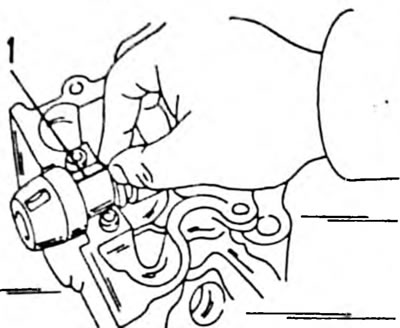
Fig. 305. Place the plastic strip (1) in the direction shown on the bearing journal
- Carefully knock down the covers of the young man and insert the bolts. Tighten the bolts in the direction from the middle outwards with a tightening torque of 18 Nm. After this, the camshaft must not be turned.
- Unscrew the bearing caps again and immediately check whether there is a PLASTIGAGE hair left on the cap. Otherwise, it will also stick to the bearing journal.
- Using the template supplied with PLASTIGAGE, measure the width of the compressed plastic hair at its widest point (Fig. 306). This characterizes the minimum bearing clearance. If the clearance is greater than 0.10 mm, the cylinder head and/or camshaft must be replaced to bring the clearance within the tolerance limits.
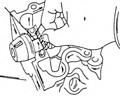
Fig. 306. Measuring the width of a crushed PLASTIGAGE hair to determine bearing play.
- To measure the axial clearance of the camshafts, clean the bearing holes in the cylinder head and the bearing caps and install the camshaft as described above. Tighten the bearing cap bolts in two or three passes.
- Install the dial indicator as shown in Figure 307 and move the camshaft in both directions, taking readings from the device. The resulting value is the axial clearance of the shaft, which should not exceed 0.25 mm. If the clearance is greater, the camshaft should be replaced. Sometimes both parts are subject to wear.
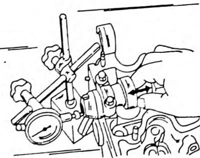
Fig. 307. Measuring the axial clearance of the camshaft
Toothed belt and gears
A belt with broken teeth must be replaced. Other defects include cracks, abrasions on the sides, or rounding of some or all of the teeth. In this case, the teeth of the gear wheels should also be checked. Hold the belt tensioner with one hand and turn the roller with the other hand. Rubbing when turning the roller requires replacing the belt tensioner. The return spring of the tensioner must have a certain length. The length is measured between the inner sides of the spring hooks, as shown in Figure 205. If the spring has become shorter than 51.93 mm, install a new spring.
Valve lifters
Measure the inner diameter of the tappet holes in the cylinder head and the outer diameter of the tappets. For this, you must have an internal and a standard micrometer. The difference should not be more than 0.10 lam. Otherwise, the tappets must be replaced, and in the worst case, the cylinder head.
(This material is taken from a resource: ToyotaMAN.ru)