
Attention! See the warnings at the beginning of the Section Depressurizing the supply system.
Fuel pump design diagram
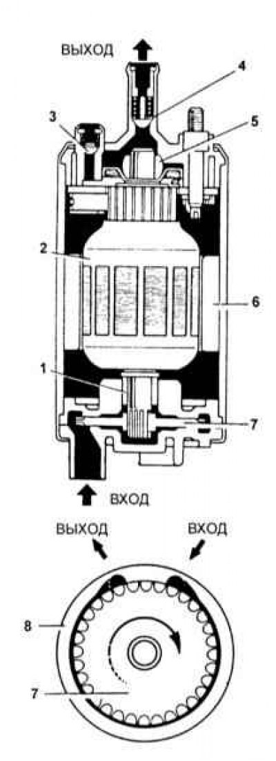
1 - Bearing; 2 - Anchor of the electric motor; 3 - Pressure reducing valve; 4 - Check valve; 5 - Bearing; 6 - Magnet; 7 - Rotor; 8 - Pump casing
Check of serviceability of functioning of the fuel pump
1. The fuel pump design diagram is shown in the illustration above.
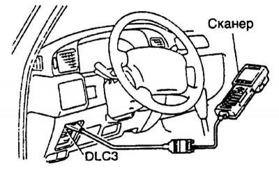
2. Connect the scanner to the diagnostic connector DLC3 (refer to accompanying illustration).
3. Turn on the ignition (do not start the engine).
4. Start the scanner function «Fuel pump check» («Test fuel pump») and follow his instructions.
5. If there is no scanner, remove the back seat and carpet (see Section Removal and installation of the fuel tank), remove the access door, and connect the pump connector to the 12-volt battery.
6. Check for fuel pressure at the pump outlet: pulsations should be felt in the hose and a murmur of fuel should be heard. In this case, the assistant listens to the operation of the pump with the fuel filler cap removed.
7. If there is no pressure, check the following:
- a. Fusible links (MAIN2.0L, AM20.3P);
- b. Circuit breakers (EFI 15 A, IGN 7.5 A);
- c. Main relay (EFI)
- d. Fuel pump
- e. ECU
- f. Wiring connectors
8. Turn the ignition key to position «Lock».
9. Disconnect the scanner from the DLC3 connector.
Checking the pressure characteristic of the fuel pump
Note. To check the fuel pressure, you will need a special pressure gauge with a wide range scale and an adapter for connecting the pressure gauge to the injection system of Toyota vehicles.
1. Prepare a special pressure gauge equipped with a connecting hose with a hollow bolt fitting and designed to measure fuel pressure in the range up to 4.2 kgf/cm2.
2. To relieve residual pressure in the fuel tank, remove the cap from its filler neck.
3. Check the battery level - the output voltage should be at least 12V (see chapter Engine electrical equipment).
4. Relieve the pressure in the supply system (see Section Depressurizing the supply system).
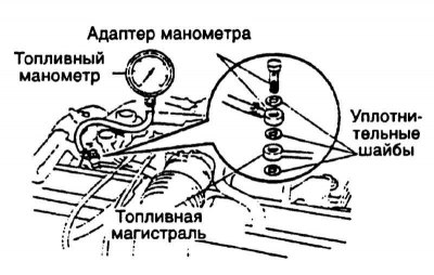
5. A special fitting is provided on the fuel line for connecting a pressure gauge, do not forget to install sealing washers on both sides of the hollow bolt (refer to accompanying illustration). Tighten the bolt to 29 Nm.
6. Connect the scanner to the DLC3 connector. Connect the battery, turn on the ignition.
7. Read the pressure gauge and compare it with the requirements Specifications. If the reading is too high, check the fuel return line and fuel filter for continuity, and replace the pressure regulator if necessary. If the pressure in the system is too low, pinch the fuel return line - if the pressure rises, replace the regulator, otherwise check the condition of the fuel supply line, fuel pump and fuel filter.
8. Start the engine. Measure the fuel pressure at idle. If the measurement result is out of range (see Specifications), check fuel pressure regulator and/or injectors.
9. Stop the engine and make sure that the system continues to maintain pressure at a level of at least 1.5 kgf / cm for five minutes2. If the pressure drops too quickly, check the regulator, pump, and injectors for signs of leaks.
10. After checking the pressure, disconnect the negative cable from the battery and carefully remove the pressure gauge with adapters. Try not to spill fuel.
11. Attach a fuel highway with new sealing rings. Tighten the bolts to a torque of 29 - 34 Nm.
12. Connect the negative cable to the battery.
13. Start the engine and check for leaks.