
Examination
Steering gear components installation details
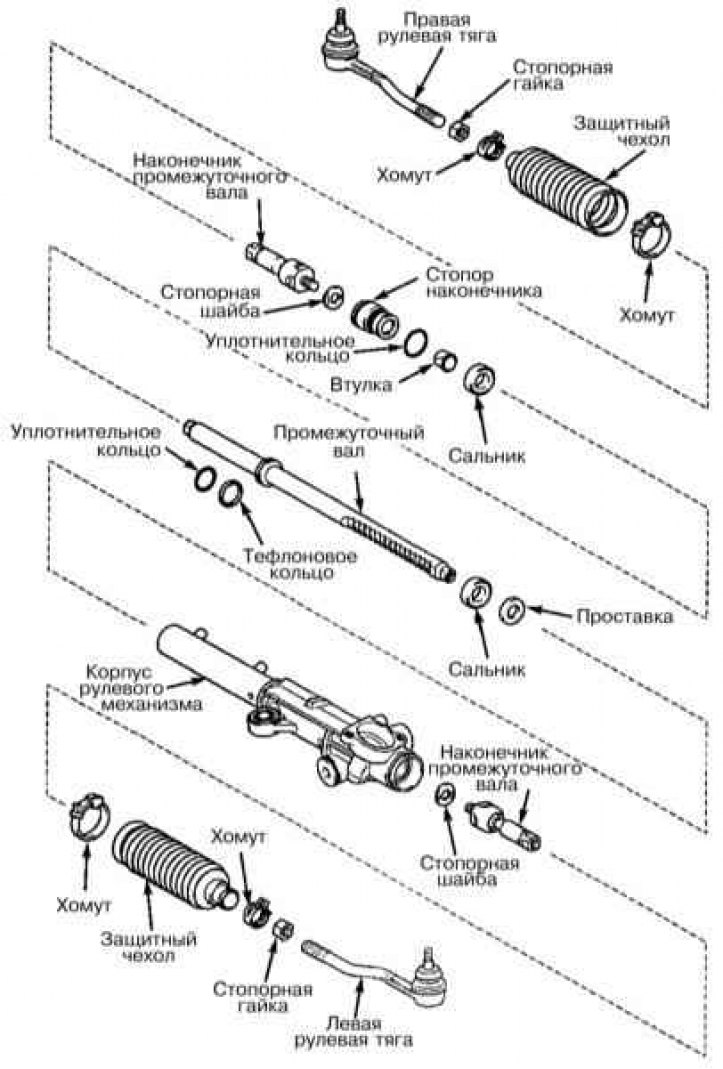
1. Through the steering rods, the force is transmitted to the steered front wheels of the car (refer to illustration above). At the same time, the required geometry of the mutual arrangement of the wheels is observed, taking into account the difference in the inner and outer turning radii. The steering drive consists of a steering mechanism and two adjustable side steering rods. The translational movement is transmitted by means of two adjustable side rods to the steering knuckles of the hub assemblies of the front wheels. The side rods are equipped with ball ends at both ends and an adjustable tubular coupling in the middle. The coupling is fixed with two clamps.
2. Bring the front wheels of the car into a straight line and lock the steering column with the ignition key.
3. Jack up one side of the vehicle so that the respective front wheel is 2-3 cm off the ground.
4. Fix the dial indicator so that its plunger rests against the front rim of the wheel, then grab the wheel with your hands at the 3 and 9 o'clock positions and pull it hard back and forth. Read the indicator reading, it should not exceed 2.7 mm. If the backlash is excessive, carefully check the condition of all docking and rotary components of the steering gear drive. If necessary, tighten the appropriate fasteners and replace defective components.
5. Check up a condition of protective covers of spherical hinges, estimate freedom of rotation of tips of steering draughts, make visual survey of components of a steering drive regarding detection of deformations and signs of mechanical damages.
Removal and installation
1. Apply the parking brake. Loosen the nuts on the corresponding front wheel. Jack up the front of the car and place it on jack stands. Remove the wheel.
2. Remove the cotter pin and loosen but do not completely remove the castellated nut of the ball stud that needs to be replaced.
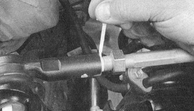
3a. If you need to replace the tip, mark its position (refer to illustration).
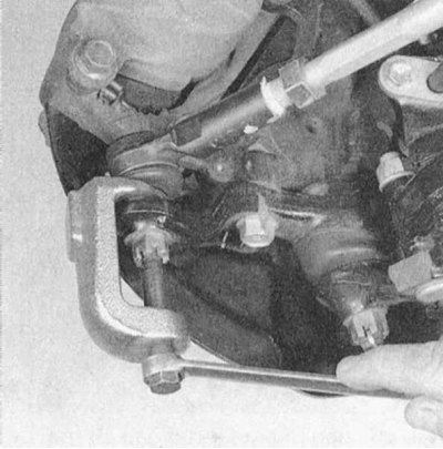
3b. Using a 2-jaw puller, release the tip from the steering knuckle assembly. Completely unscrew the castle nut and separate the tip from the knuckle (refer to illustration).
4. If the entire link needs to be replaced, separate the tip from the intermediate shaft assembly (see paragraphs 2 and 3).
5. Before replacing, measure the distance from the cut of the adjusting sleeve to the center point of the ball stud of the handpiece. Record the measurement result, then loosen the coupling clamps and unscrew the tip.
6. Lubricate the threads of the new lug with chassis grease. Screw the tip into the sleeve to the same depth (see paragraph 5).
Note. The number of visible threads of one tip should not differ from the number of visible threads of the second by more than three. Do not tighten the mounting clamps yet.
7. Screw on the castle nut of the ball stud, tighten it to the required force and fix it with a cotter pin, if necessary tightening the nut a little more to align the holes for installing the cotter pin.
Note. If the ball stud begins to rotate when the nut is tightened, use large pliers to press into the conical seat.
8. Tighten the nuts of the mounting collars. The bolt should be deployed almost horizontally, and the groove of the adjusting sleeve should be misaligned with the clamp locks.
9. Replace the wheels, lower the vehicle to the ground and tighten the wheel nuts to the required torque (see chapter Vehicle settings and routine maintenance). Drive the vehicle to a workshop to have the front wheel alignment checked and adjusted.