
- Loss of engine power.
- Reducing the amount of coolant. White exhaust gases.
- Oil loss.
- The presence of coolant in the engine oil. Increasing the oil level, not lowering it. Gray engine oil. Bubbles on the oil level indicator, decrease in oil viscosity.
- The presence of engine oil in the coolant.
- Foaming coolant.
- Lack of compression in two adjacent cylinders.
Removing
Disconnect ground cable (-) from the battery.
Attention: This erases the entries in the memory of the on-board computer, in particular, the fault record and the radio code. Before disconnecting the battery, read the contents of the section "Removing and installing the battery".**
Remove air filter.
Drain coolant.
Disconnect the gas line.
Disconnect the following vacuum hoses, having previously marked them:
- hose at the box with activated carbon;
- hose at the brake booster;
- hose to the fuel gauge at the right suspension strut;
- a hose to the vacuum switch of the injection system at the bulkhead, separating the engine compartment from the passenger compartment;
- hose to injection vacuum switch at right engine mount;
Disconnect all electrical wires going to the engine, having previously marked them;
- combined oxygen sensor plug (lambda probe);
- combined plug of the ignition system at the ignition distributor;
- coolant temperature indicator plug;
- oil pressure switch plug;
- combined plug of the thermal relay of time;
- combined plug of the coolant temperature indicator sensor;
- combined vacuum sensor plug;
- combined plug for injection valves and cold start valve;
- combined throttle potentiometer meter;
- vacuum sensor on the right above the engine support;
- cylinder head mass cable;
- plug and connectors on the rear wall of the generator;
- plug-in connection of a plait of wires behind the right depreciation rack;
Unscrew the bolts securing the wiring harness at the exhaust manifold and move the harness to the side so that it does not interfere with further work on removing the engine.
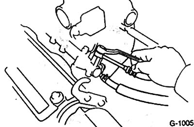
Loosen the bolt securing the fuel supply line to the distributor line, cover the connection with a rag and relieve pressure. After that, disconnect the pipeline completely and muffle it. Disconnect the fuel return line and plug it. Collect leaked fuel in a container.
Disconnect all coolant hoses from the coolant outlet housing after opening the clamps.
Disconnect intake air heater coolant hoses and air hoses from throttle body.
Remove intake manifold bracket.
Loosen the mounting bolts and remove the exhaust pipe exhaust systems.
1.6L 4A-GE engine: Remove the right and left exhaust manifold brackets.
Loosen the nuts securing the cylinder head cover, remove the sealing washers and the cover.
Remove toothed belt.
1.6L engine (4A-F, 4A-FE, 4A-GE, 4A-GEL): Remove camshafts.
1.6L engine (4A-GE, 4A-GEL):
Remove right engine mount.
Remove rear toothed belt cover.
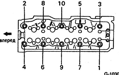
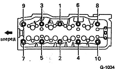
Unscrew the cylinder head bolts in three steps in order from 1 to 10. For the first step 1/2 turn, for the second step a full turn, for the third step, unscrew completely. Arrow with the inscription "forward" The figure indicates the direction away from the gearbox. (Bolt loosening sequence for 1.3L engines up to 7/84 and 1.6L engines: 4-3-2-1-8-7-6-5-9-10).
Attention: Loosening bolts in random order can lead to deformations and cracks in the cylinder head.
Check that all hoses and wires from the cylinder head to the body and engine are disconnected.
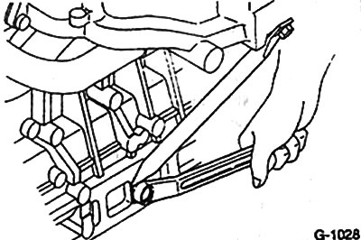
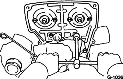
With the help of an assistant, lift the cylinder head. If the cylinder head is not removed, then you can use the pry bar by inserting it between the cylinder head and the cylinder block into the groove provided for this (see fig.).
Attention: After removal, the cylinder head must not be placed on the mating surface. This can damage open valves. The cylinder head should be mounted on wooden blocks.
Installation
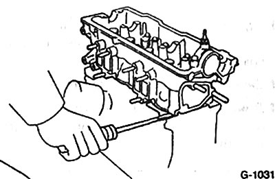
With a scraper, clean the block and cylinder head before installing from the remnants of the gasket. In this case, damage to the mating surfaces must not be allowed. Make sure that seal residues do not get into the cylinder block bores by covering them with a cloth.
Check for oil in the cylinder head bolt holes. If oil is present, blow it out with compressed air. If compressed air is not available, a screwdriver can also be used.
Caution: The oil must be removed in any case.
Check the flatness of the mating surface of the cylinder head using a ruler and feeler gauge.
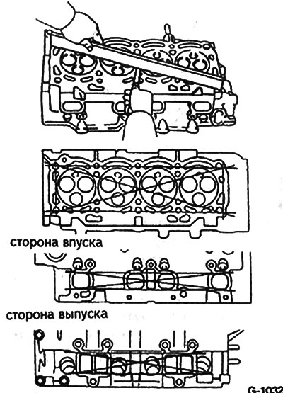
Check the deformation of the mating surfaces along the axes indicated in Figure G-1032. The non-flatness of the surfaces adjacent to the cylinder block of the exhaust manifold must not exceed 0.05 mm (for a 1.6 liter engine, the flatness on the exhaust manifold side must not exceed 0.1 mm). If the flatness exceeds the specified values, then the cylinder head must be replaced.
Check for cracks in the cylinder head. If there are cracks, the cylinder head is replaced.
Check coolant, oil and fuel hoses for cracks and pores. Replace if necessary.
Install the cylinder head gasket with the letters and numbers marked on it facing up.
Check valves and their seats for wear or damage.
Cover the bearing surface of the bolt heads and threads with a thin layer of grease.
Screw in the 10 cylinder head bolts by hand until they stop. - Then tighten the bolts in three steps in the sequence from the first to the tenth.
- 1 reception - with a torque wrench with a force of 30 Nm
- 2 reception - with a torque wrench with a force of 50 Nm
- 3 reception - 1/4 turn (90°) hard key without interception.
1.3L engines up to 7/84 and 1.6L engines
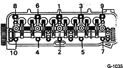
Screw in the 10 cylinder head bolts by hand until they stop. Then tighten the bolts in three stages in sequence from the first to the tenth with the following efforts (Tightening torques for the 4A-GE engine are shown in brackets):
- 1 reception - with a torque wrench with a force of 30 Nm (15 Nm)
- 2nd reception - with a torque wrench with a force of 45 Nm (30 Nm)
- 3rd reception - with a torque wrench with a force of 60 Nm
Caution: Cylinder head bolts must be tightened with great care. Before tightening, the torque wrench must be checked for accuracy. The tightening sequence must be followed.
1.6L engine (4A-F, 4A-FE, 4A-GE, 4A-GEL): Install camshaft.
1.6L engine (4A-GE, 4A-GEL)
Install rear toothed belt cover.
Install the right engine mount.
Put on toothed belt.
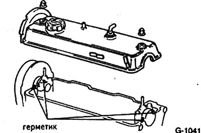
Install the head cover. Apply sealant #102 (ET-Nr.08826-00080) or some other silicone based sealant as shown in Figure G-1041.
Install intake manifold brackets.
1.6L 4A-GE engine: Install the left and right exhaust manifold supports.
Install and bolt the exhaust pipe to the exhaust system.
Connect and secure all electrical wires, vacuum hoses and cooling system hoses according to the marking.
Push the fuel return hose onto the fuel distribution line and secure with clamps. Fasten the fuel supply hose to the line with a force of 30 Nm by installing a new gasket.
Install and adjust gas draft.
Check the density of antifreeze in the coolant. Top up if necessary.
Change engine oil.
Install air filter.
Connect ground cable (-) to the battery.
If there is a clock, set it and enter the security code into the radio.
Check ignition timing if necessary adjust it.
Check engine idling. If necessary adjust.
Start and warm up the engine. Check coolant level and connections for leaks.
Check valve clearance.