
Attention! Proceed with the procedure only after the final cooling of the power unit.
Two halves of the inlet pipeline and its components
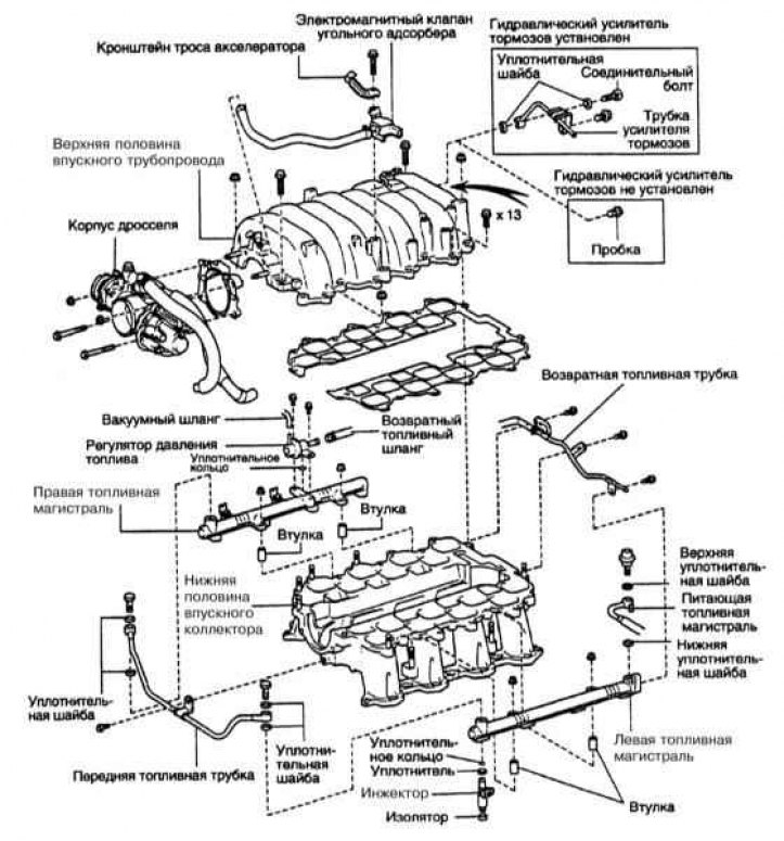
On 2UZ-FE engines, an intake manifold is installed, consisting of two parts. Top part (Toyota calls it an intake plenum) contains throttle body. The lower part is the intake manifold itself and is attached to the cylinder head (refer to illustration above). In the lower part of the pipeline, fuel injectors and a line are installed.
Attention! Be careful when handling light aluminum parts, they are easily damaged. Note that in this engine the starter is attached to the bottom half of the intake manifold. The starter is facing backwards, engaging the flywheel at the top.
Warning! After switching off the ignition, there is residual pressure in the fuel system. Pressure must be relieved before disconnecting fuel lines to avoid personal injury.
Removing
1. Depressurize the fuel system (see chapter Power supply and exhaust systems).
2. Drain the coolant.
3. Disconnect the accelerator cable, AT throttle cable (with appropriate equipment) and tempostat cable (with appropriate equipment) from the throttle body.
4. Disconnect fuel lines.
5. Disconnect from the inlet pipeline following sockets:
- Throttle position sensor (TPS)
- Gas Pedal Position Sensor Connector
- Throttle Motor Connector
- EVAP charcoal canister purge control connector
- Eight fuel injector connectors (tag first)
- Coolant temperature indicator sensor and coolant temperature indicator sensor connectors
- Eight (tag first) ignition coil connectors
- Two lambda probe connectors
6. Tag and disconnect the following hoses from the intake manifold:
- Vacuum hose from fuel pressure regulator
- PCV hose from PCV valve on left cylinder head
- Three EVAP charcoal canister purge hoses
- Power steering vacuum hoses
- If the vehicle is not equipped with hydraulic brake booster, disconnect the vacuum hose of the vacuum booster
7. Disconnect the accelerator cable from the throttle body and remove the three clips.
8. Disconnect the cooling system bypass hose from the front bypass fitting.
9. Disconnect the engine wiring harness where it is attached to the right fuel line.
10. Turn away three bolts of fastening of protection of conducting of the engine from the back bypass union of the cooling system on both heads of cylinders.
11. Disconnect the tires from both cylinder heads «masses».
12. Remove the DLC1 diagnostic connector from the throttle body cover bracket and remove the bracket from the intake manifold.
13. Give two nuts and remove an accelerator cable bracket from the inlet pipeline.
14. Turn away nuts and bolts and remove the inlet pipeline entirely together with fuel highways.
Installation
1. Scrape off all traces of sealant and old gasket material from the mating surfaces of the pipeline and cylinder heads, then wipe the surfaces with a rag soaked in acetone. Check the flatness of the mating surfaces with a steel ruler and a set of flat feelers. The permissible curvature of the plane is 0.15 mm. If the permissible value is exceeded, the parts must be replaced.
2. Check new gaskets. Factory gaskets are labeled with white paint to indicate «top», Carefully align the channel holes and gaskets. After installing two new gaskets, carefully lower the pipeline into place.
3. Tighten the fastening bolts and nuts with a force of 18 Nm.
4. Install the remaining components in the reverse order of their dismantling.
5. Prime the cooling system. Start the engine and check it for signs of developing fuel, coolant, and vacuum losses.