
Note. If defects in the protective cover are detected, the condition of the corresponding CV joint must be carefully studied. Often, fully remanufactured driveshaft assemblies can be purchased on a trade-in basis, which greatly simplifies the situation and saves time. Before proceeding with the dismantling of components, conduct marketing by finding out the prices of the necessary parts. Compare them with the cost of purchasing refurbished builds. Remember that the outer CV joint is not subject to disassembly and changes as an assembly with the shaft.
Remove the drive shaft (see Section Removal and installation of power shafts).
Disassembly
Drive Shaft Assembly Components
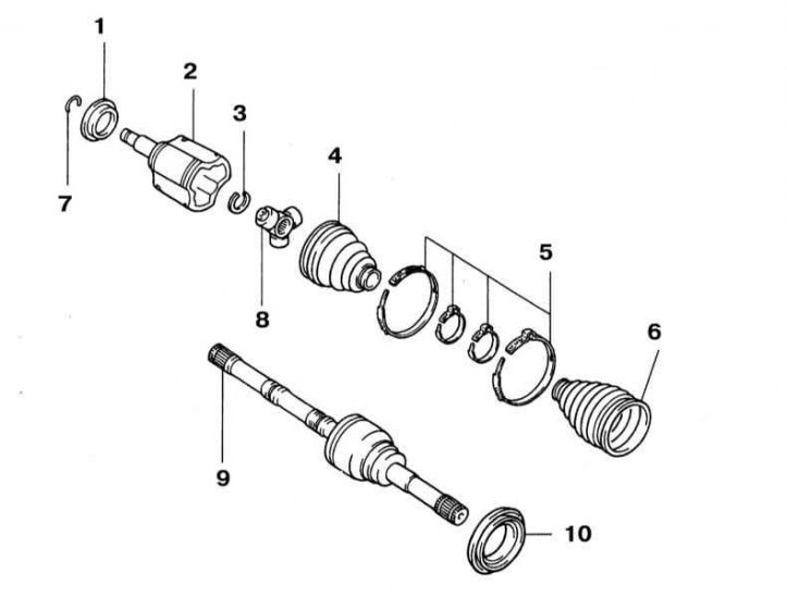
1 - duster; 2 - Housing of the inner CV joint with a trunnion; 3 - Retaining ring; 4 - Protective cover; 5 - Bandage tapes; 6 - Protective cover; 7 - Retaining ring; 8 - Tripod assembly; 9 - Assembling the outer CV joint with the drive shaft; 10 - duster
1. Clamp the shaft in a vise with soft jaws. Check the joint for radial play, indicating wear on the internal components. Check up smoothness of a course of both hinges in all directions provided by their design. If the protective cover is damaged, disassemble the CV joint, thoroughly wipe its components and evaluate their condition.
2. Using a small screwdriver, pry out the locking tabs and remove the protective boot's retaining straps.
3. Pry off the edge of the cover with a screwdriver, remove it from the hinge assembly (old and damaged covers can simply be cut off) (refer to illustration above). Remove the hinge housing from the tripod assembly.
4. Mark the position of the tripod assembly on the shaft stub.
5. Remove the retaining ring.
6. Using a brass drift, knock the tripod assembly off the shaft stub.
7. If you have not cut them yet, remove the protective covers of both hinges. Wrap a protective layer of duct tape around the splined inner shaft stub to protect the new boots from damage when they are pushed onto the shaft.
Note. The outer CV joint cannot be disassembled.
Examination
Thoroughly wash all components, including the outer CV joint assembly, in solvent, removing all traces of old grease from them. Assess the condition of the working surfaces of the bearings of the tripod assembly and mating surfaces in the inner hinge housing. It is not possible to directly inspect the working surfaces of the outer and inner bearing races of the outer CV joint, however, the condition can be indirectly judged by the appearance of the balls, turning the hinge, evaluate the condition of all the balls. If the balls are not deformed or otherwise damaged, then the cages can also be considered in good condition and the joint should be reused. In case of failure of the components of the inner CV joint, the hinge assembly can be replaced. The outer CV joint changes as an assembly with the shaft.
Assembly
1. Put on the shaft the protective covers of both CV joints with the bandage tapes of their fastening, then put the tripod assembly in its regular place, securing it with a retaining ring. Pack grease into the bearings of the tripod assembly and into the bottom of the hinge housing cavity. Thread the end of the shaft with the tripod assembly installed inside the hinge body and stuff the remaining grease into the cavity of the latter.
2. Pull the boot over the hinge assembly, making sure its edges are securely seated in the receiving grooves. Adjust shaft length as required Specifications.
3. Pry up the outer edge of the hinge to equalize the pressure under it, then tighten the fastening collars / bandages.
4. Install the shaft assembly on the vehicle (see Section Removal and installation of power shafts).