
Installation details of the hub with manual disengagement of the front wheel drive
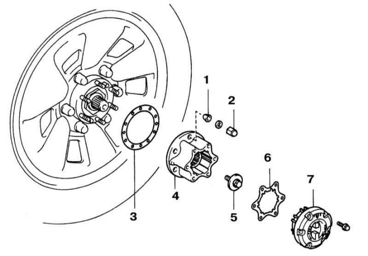
1 - Conical washer; 2 - Nut; 3 - Sealing gasket; 4 - Hub housing; 5 - Bolt; 6 - Sealing gasket; 7 - Hub cap
Hub Lock Components with Manual Drive Disengagement
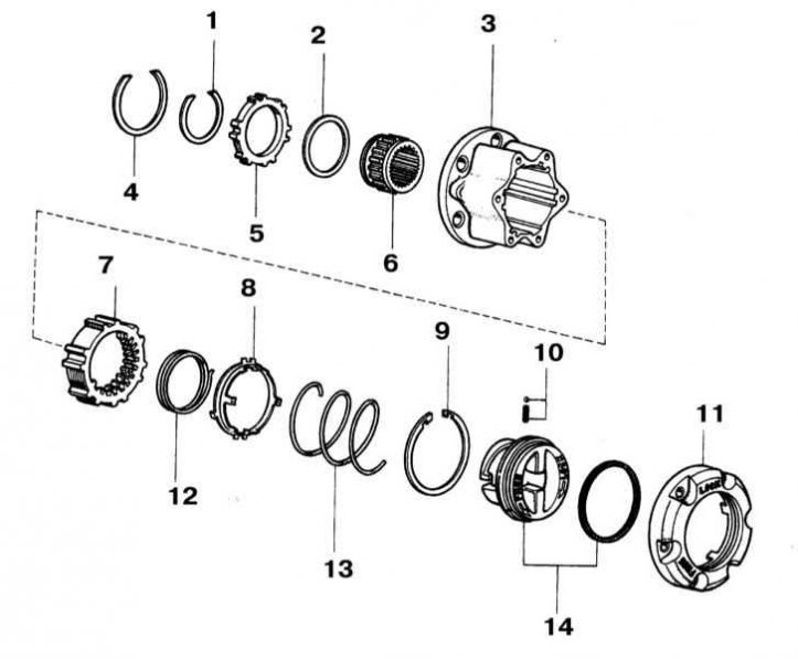
1 - Retaining ring; 2 - Remote ring; 3 - Hub body; 4 - Retaining ring; 5 - Toothed ring of the hub; 6 - Internal hub; 7 - Clutch of the hub lock; 8 - carrier; 9 - Retaining ring; 10 - Steel ball with spring; 11 - Hub cover; 12 - Spring; 13 - Spring; 14 - Control handle with stuffing box
1. Move the hub cap to the Free position (Free).
2. Turn out fixing bolts, then remove a cover and internal components of a nave (refer to the illustration Details of the installation of the hub with manual disengagement of the front wheel drive).
3. If equipped, remove the bolt from the end of the drive shaft.
4. Give nuts of fastening of the case of a nave.
5. Use a brass drift to knock the cone washers off the assembly.
6. Remove the hub housing with the splined drive shaft trunnion.
7. Failure of the locks for turning on the hub drive most often occurs due to the ingress of dirt and moisture into them. If it becomes necessary to further disassemble the hub, try to pay close attention to the order and method of installation of each of the components. Place the components on the workbench in the order in which they were removed. Wipe each part in turn, lubricate the components with universal grease, then install them in their regular places (refer to illustration Components of a hub lock with manual drive disengagement).
8. Installation of the hub components is carried out in the reverse order of their dismantling. Remember to replace the seals and lubricate the splines of the inner liner with multipurpose grease. Before installation, the control handle on the hub cover must be turned to the Free position, make sure that the tongues of the carrier are correctly engaged with the sections of the assembly body without teeth.