
Note. You will need a press or a large vise to replace the universal joints.
1. Remove the cardan shaft (see Section Removal and installation of cardan shaft).
2. Transfer the cardan shaft to a vise-equipped workbench.
3a. Mark the position of the clamp relative to the shaft (refer to accompanying illustration).
3b. Then remove the retaining rings (refer to accompanying illustration).
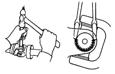
Note. On the models considered in this Manual, the bearings of the universal joint crosses can be equipped with retaining rings of both external and internal designs. The outer rings are removed with pliers; a drift and a hammer will be required to remove the inner circlips from their mounting grooves.
4. Press a piece of pipe or socket of the appropriate diameter against the cup of one of the bearings (the mandrel must have the same inner diameter as the cup). Install a mandrel of slightly smaller diameter from the opposite end of the cup and, holding the assembly in a vise, squeeze the cup out (inside the larger mandrel) approximately 25 mm.
Note. Try not to force the cup completely out of its seat in the jaw of the yoke.
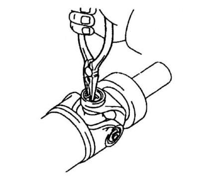
5. The final removal of the cup is done with tongs.
6. In the same manner, squeeze out the opposite bearing cup.
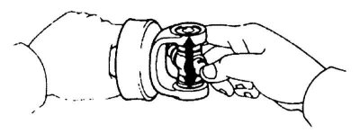
7. Remove the swivel assembly from the collar and wipe thoroughly. Make sure that there are no nicks or scratches inside the seats in the jaws of the collar assembly.
8. Pack new bearing cups with grease to hold rollers.
Note. Instructions for bearing lubrication are usually included in the packaging of the standard repair kit and must be strictly followed.
9. Insert the swivel assembly inside the clamp and partially fill the cup of one of the bearings into the seat. If the joint is equipped with a grease fitting, make sure that it is turned in the same direction as the fitting of the joint located on the opposite end of the shaft.
10. Enter the hinge body into the bearing cup, then partially fill the collar with the second cup. Align the hinge between the cups, then finally press the latter into the clamp, try not to damage the anthers.
11. Establish lock rings, in case of need sharply knock on a collar for the purpose of shrinkage of rings in grooves. If the ring does not sit even after tapping the clamp, therefore, one of the needle bearings of the spider has jammed, disassemble the joint and repeat the procedure.
12. Check the axial play in the hinge (refer to accompanying illustration) – if it is more than 0.05 mm, select suitable retaining rings. Rings are installed in pairs of the same thickness on the same axis so that there is no vibration.
13. Install the driveshaft on the car (see Section Removal and installation of cardan shaft).
14. If the joints are equipped with grease fittings, pack them with grease (see chapter Vehicle settings and routine maintenance).
15. Remove the props and lower the vehicle to the ground.