
You can carry out simple checks on the drive and connections yourself. A more detailed check and elimination of serious malfunctions is carried out in a car service. The locks are controlled by reversible electromagnets mounted in the door niches.
Lock switches have 2 positions: Lock and Unlock. From the switch, the control unit receives a signal to unlock or lock the door. The control unit reverses the polarity of the signal in accordance with the position of the switch, as a result, the outputs of the solenoid coil are connected either to ground or to +12 V power.
On some cars, anti-theft devices are built into the door locks.
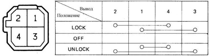
Diagram for checking the electric door lock switch on FJ60, 62 vehicles and designation of connector pins
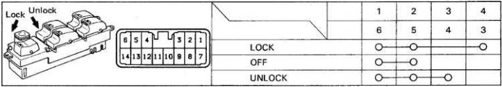
FJ80 Motor Door Lock Switch Test Diagram and Connector Pin Designation
Examination
1. The fuses and circuit breakers are checked first.
2. When the lock drive is actuated, a click should be heard in any position of the switch.
3. Check the contact closure of the door lock switches according to the attached diagram. If the contacts do not close according to the attached diagram, then replace the switch.
4. If the switch is OK, then check for an open in the wires connecting the control unit, solenoids and switches.
5. Check the ground connection of the control unit and switches.
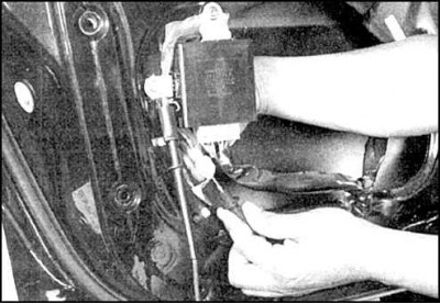
6. If only one solenoid does not work, then check the presence of voltage on it by removing the door lining. In the Lock position, there should be voltage on one of the wires. After moving the switch to the Unlock position, voltage should be on the opposite wire.
7. If there is voltage, replace the solenoid.
8. Otherwise, check the relay or wire between the control box and the solenoid. As a rule, this wire breaks when closing and opening the door.