
Diagram for checking the driver's door lock main switch
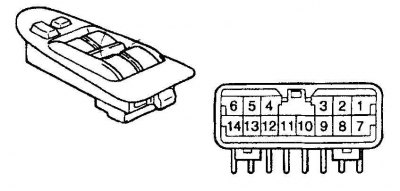
| Switch position | Numbers of tested pins | The presence of a chain |
| Lock | 2 – 4 | There is a chain |
| Off | – | no chain |
| Unlock | 3 – 5 | There is a chain |
Passenger's Door Lock Main Switch Test Diagram
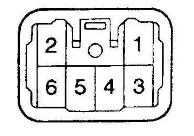
| Switch position | Numbers of tested conclusions | The presence of a chain |
| Lock | 3 – 6 | There is a chain |
| Off | – | no chain |
| Unlock | 3 – 5 | There is a chain |
The structure of the electric drive includes switches, a lock drive, a control unit and wires. The control unit is mounted under the instrument panel, to the right of the fuse box. You can carry out simple checks on the drive and connections yourself. A more detailed check and elimination of serious malfunctions is carried out in a car service.
The locks are controlled by reversible electromagnets mounted in the doors. Lock switches have 2 positions: Lock and Unlock. From the switch, the control unit receives a signal to unlock or lock the door. The control unit reverses the polarity of the signal in accordance with the position of the switch, as a result, the outputs of the solenoid coil are connected either to ground or to +12 V power.
On some cars, anti-theft devices are built into the door locks.
The fuses and circuit breakers are checked first.
When the lock drive is actuated, a click should be heard in any position of the switch.
Check the contact closure of the door lock switches (refer to Driver's Door Lock Master Switch Test Diagram and Passenger's Door Lock Master Switch Test Chart). If the contacts do not close according to the attached diagram, then replace the switch.
If the switch is OK, then check for an open in the wires connecting the control unit, solenoids and switches.
Check the ground connection of the control unit and switches.
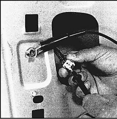
If only one solenoid does not work, then check the presence of voltage on it by removing the door lining. In the Lock position, there should be voltage on one of the wires. After moving the switch to the Unlock position, voltage should be on the opposite wire.
If there is voltage, replace the solenoid.
Otherwise, check the relay or wire between the control box and the solenoid. As a rule, this wire breaks when closing and opening the door.
IR remote unlocking system
The system consists of an IR transmitter that hits a receiver that unlocks the door. On some vehicles, this system also triggers an anti-theft system "fright", including headlights and horn.
If the LED indicator on the transmitter does not light when the button is pressed, the battery should be replaced. As the battery discharges, the actuation distance of the unlocking system decreases.
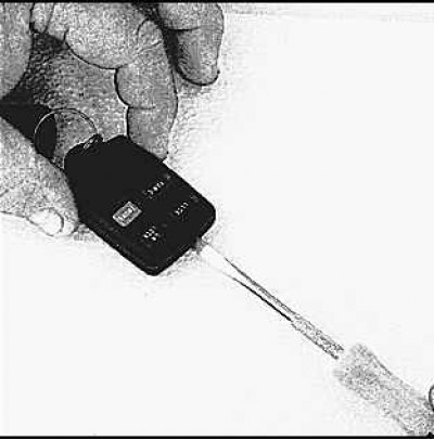
To replace the battery, pry and separate the case halves.
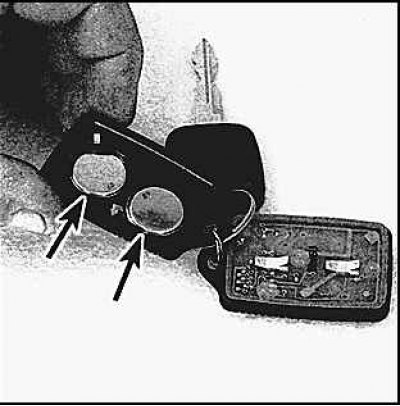
Install new batteries with correct polarity.