
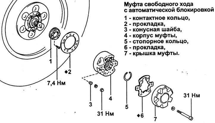
Removing
1. Removing the coupling cover.
A) Set the ignition switch to position "ON". Set the clutch lock switch to position "OFF", to unlock (FREE) freewheel clutches.
b) Using a special wrench, unscrew the six bolts securing the cover.
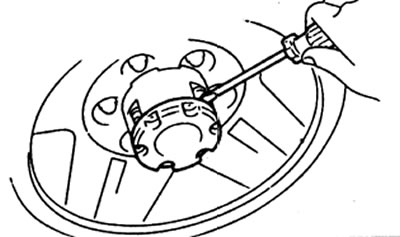
V) Insert a flat-blade screwdriver between the coupling housing mounting nut and the cover, and remove the cover.
Attention:
- Alternately evenly slide the coupling cover, applying the same force at four points.
- Do not damage or scratch the coupling cover.
- To avoid deformation, do not use a hammer or similar tool when removing the coupling cover.
G) Remove the gasket from the clutch cover.
2. Removing the clutch housing.
A) Remove the circlip from the clutch housing.
b) Loosen the four nuts securing the clutch housing and remove the washers.
V) Using a brass rod and hammer, remove the cone washers from the coupling housing mounting bolts.
Caution: Be careful not to damage the coupling body when removing the cone washers.
G) Remove the clutch housing along with the gasket.
Attention: do not damage the brush when removing the housing.
3. Using a special key, unscrew the three fixing screws and remove the contact ring.
Examination
1. Checking the clutch housing,
A) Measure the brush height.
Standard Height:
- A - 6.5 mm
- B - 4.7 mm
Minimum allowed height:
- A - 4.2 mm
- B - 4.2 mm
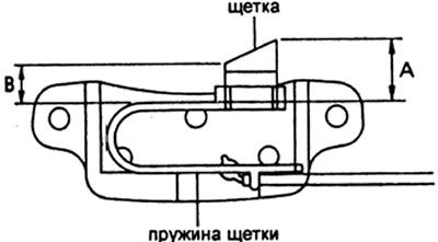
b) If the brush height is less than the minimum, replace the clutch housing.
Attention:
- Do not remove the brush from the holder.
- Do not damage the brush spring.
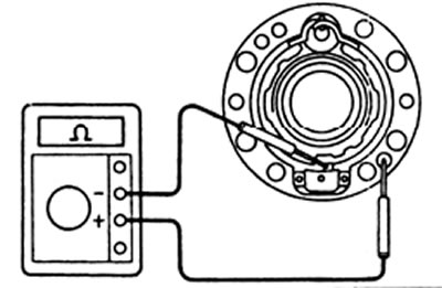
2. Checking the clutch assembly.
A) Check for continuity between brush and clutch housing.
b) If there is continuity, replace the clutch housing.
Installation
1. Clean bolts and bolt holes with solvent.
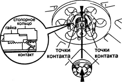
2. Installation of the slip ring.
A) Clean slip ring, lock nut, drive shaft and steering knuckle shaft.
b) Align the protrusion of the slip ring with the recess of the steering knuckle shaft and install the ring on the lock nut.
V) Make sure that the contacts of the ring are firmly pressed against the axis of the steering knuckle.
Attention: make sure that there is no oil and grease in the contact points.
G) Using a special wrench, install the three screws securing the slip ring.
Tightening torque - 7.4 N.m
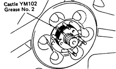
3. After cleaning the slip ring again, apply a thin layer of Lubricant evenly around the circumference of the slip ring.
Lubrication: Part No. 08867-02007 Castle Body Grease IV.
Caution: Do not apply any lubricant to the slip ring other than Castle YM102 No. 2.
Note:
- Apply approximately 2-3 grams of lubricant.
- If no lubricant has been applied, or a lubricant other than the one specified above has been applied, there may be a lack of conductivity at low temperatures or premature wear of parts.
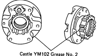
4. Apply a thin layer of lubricant evenly to the contacts (sliding) parts of the housing and coupling cover. Lubrication: Part No. 08887-02007 Castle Body Grease IV.
5. Installing the clutch housing.
A) Align the dowel pins on the hub with the V-notches in the new gasket and install the gasket.
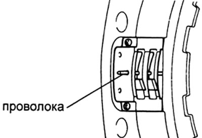
b) Using a wire, fix the brush as shown in the picture.
Caution: Do not apply oil or grease to the brush.
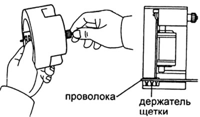
V) Make sure the brush is held in the holder.
G) Install the clutch housing onto the wheel hub. Install the cone washers and washers, tighten the fastening nuts.
Tightening torque - 31 N.m
Note: Make sure the brush is locked before installing the clutch housing.
d) Remove the wire from the clutch housing.
6. Installing the retaining ring.
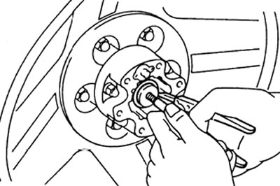
A) Wrap the bolt in the axle shaft and pull it out.
b) Install the retaining ring, then remove the bolt from the axle shaft.
7. Fitting the coupling cover.
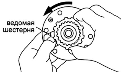
A) While holding the driven gear, turn the clutch hub counterclockwise to set the mechanism to the position "FREE" (unlocked)
b) Remove the protective film from the new gasket and install the gasket on the clutch cover.
Attention:
- Install the gasket with the adhesive surface (on which the film was) to the clutch cover.
- Make sure that there are no bumps and that the gasket is properly aligned.
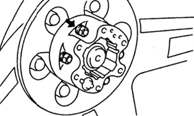
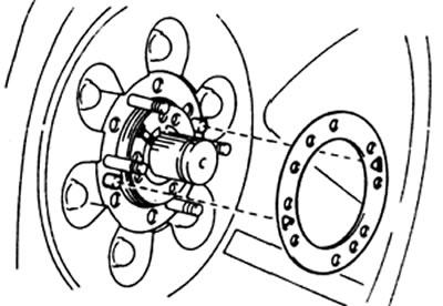
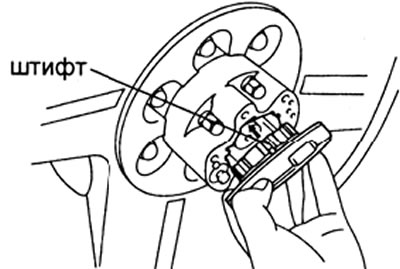
V) Install the coupling cover onto the body, aligning the pin on the cover with the hole in the body as shown.
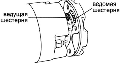
G) Align the teeth of the driven gear and the drive gear and install the clutch cover.
Attention: make sure that the cover does not move relative to the body when pressed by hand.
Note: if there is a gap between the cover and the coupling body, when the cover fastening bolts are tightened, parts of the locking mechanism may be damaged. If a gap is found between the cover and the body, follow the steps (A) - (G) and check that there is no gap.
d) Apply sealant to the threads of the clutch cover bolts.
Sealant: Part No. 08833-00080, Tree Bond 1344, Loctite 242 or equivalent.
e) Using a special wrench, tighten the six bolts securing the clutch cover.
Attention:
tighten in two passes:
- Tighten the bolts diagonally to 20 Nm.
- Tighten the bolts in a diagonal pattern to 31 N.m.
8. Check clutch operation.