
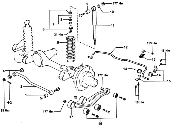
Front suspension. 1 - bushing, 2 - Panhard rod, 3 - cotter pin, 4 - pillows, 5 - spring, 6 - washers, 7 - pillows, 8 - limiter, 9 - sleeve, 10 - washer, 11 - shock absorber, 12 - stabilizer, 13 - stabilizer bar, 14 - stabilizer pad, 15 - stabilizer mounting bracket, 16 - bushing, 17 - longitudinal rod.
Spring and damper
Removing
1. Hang out the car and establish support racks under a frame.
2. Remove wheels.
3. Removing the shock absorber.
A) Place a support under the front axle housing.
b) While holding the upper shock absorber mounting bolt, remove the nut.
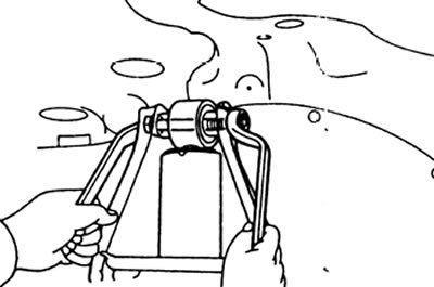
V) Unscrew the lower shock absorber mounting nut, remove the pillows, washers and limiter. Remove shock absorber.
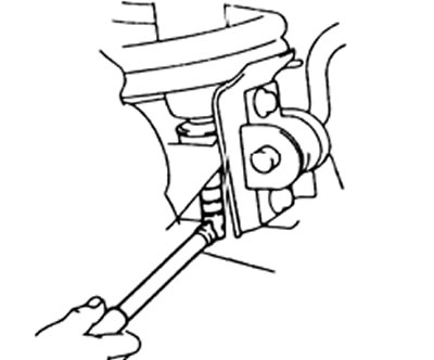
4. Turn away two bolts of fastening and disconnect the stabilizer from the forward bridge.
5. Lower the car on the jack, substituting the support under the front axle housing.
6. Removing the spring.
A) Compress the spring using the special tool.
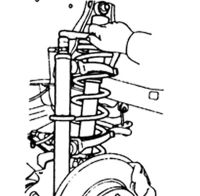
b) Squeeze the shock absorber.
V) Remove the spring together with the shock absorber.
Checking the operation of the shock absorber
1. When pressing the shock absorber, check the rebound stroke is even and there is no abnormal resistance or noise.
2. Compress the shock absorber to its full travel, then release it and check the speed of the rebound travel.
Installation
1. Installing the spring.
A) Compress the spring using the special tool.
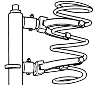
b) Squeeze the shock absorber.
V) Install the spring together with the shock absorber in place.
G) Align the end of the spring with the seat.
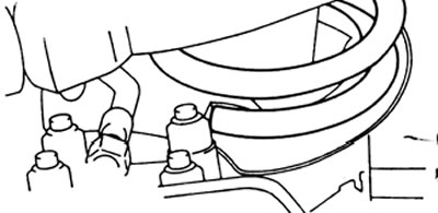
2. Connect the stabilizer to the front axle and tighten the two mounting bolts.
Tightening torque - 18 N.m
3. Installing the shock absorber.
A) Install the washers, pads and stopper on the shock rod and connect the shock to the axle. Tighten the fastening nut.
Tightening torque - 31 N.m
b) Insert the bolt from the front of the vehicle.
V) Install the nut and washer. While holding the bolt, tighten the shock absorber mounting nut.
Tightening torque - 177 N.m
Panhard rod
Removing
1. Hang out the car and establish support racks under a frame.
2. Place a support under the crankcase with the front mosh.
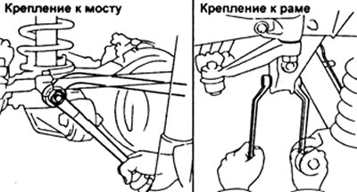
3. While holding the Panhard rod on the jack, remove the cotter pin, unscrew the nut and disconnect the rod from the front axle. Remove cushions from drawbar.
4. Turn away a nut and disconnect draft Panhard from a frame of the car.
Replacing the inner sleeve
1. Using a special tool and a press, press the bushing out of the Panhard rod.
2. Using the special tool and a press, press the new bushing into the Panhard rod.
Note: The sleeve must not be lubricated when pressed in.
Installation
1. Temporarily secure the Panhard bar to the frame with a bolt and nut.
2. Using a bolt, pads and nuts, temporarily connect the Panhard rod to the front axle.
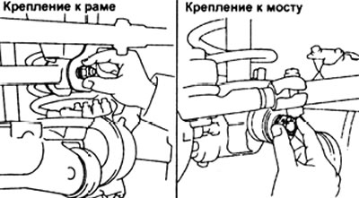
3. Lower the vehicle and rock it up and down to stabilize the suspension.
4. Hang out the forward bridge of the car by means of a jack.
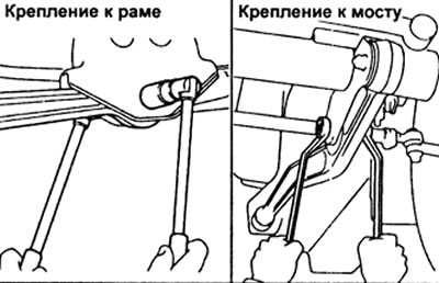
5. Tighten the bolt and nuts securing the Panhard rod to the frame and axle.
Torque:
- fastening to the frame - 143 N.m
- fastening to the bridge - 98 N.m
6. Install a new cotter pin on the Panhard rod-to-axle nut.
Longitudinal bar
Removing
1. Jack up the car and move the support legs under the frame.
2. Place a support under the front axle housing.
2. Removing the longitudinal bar.
A) Place a support under the longitudinal bar.
b) Loosen the bolt and nut on the side of the frame.
V) Turn away bolts and nuts of fastening from the forward bridge and then remove a longitudinal bar of a suspension bracket.
Installation
1. Temporarily attach the trailer bar to the vehicle frame with a bolt and nut.
Note: the bolt is inserted from the outside.
2. Temporarily connect the trailing bar to the front axle with two bolts and nuts.
Note: the bolts are inserted from the outside.
3. Lower the vehicle and rock it up and down to stabilize the suspension.
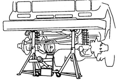
4. Hang out the forward bridge of the car by means of a jack.
Attention: in order to work safely, install support stands under the frame.
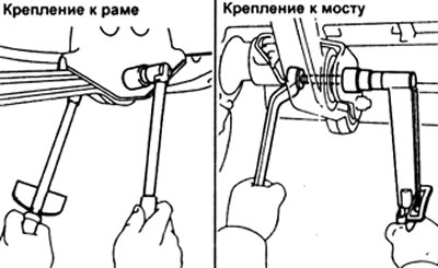
5. Tighten the bolts and nuts securing the longitudinal bar.
Tightening torque - 177 N.m
Attention: Lower the vehicle before tightening the mounting nuts to load the front axle.
Stabilizer
Removing
1. Hang out the car and establish support racks under a frame.
2. Place a jack under the front axle housing to release voltage from the stabilizer.
3. Removing the stabilizer.
A) Turn away bolts of fastening of an arm of the stabilizer and disconnect the stabilizer from the forward bridge.
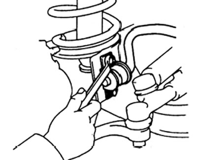
b) While holding the stabilizer, unscrew the strut mounting nut and disconnect the stabilizer from the frame.
V) Turn away bolts of fastening, remove pillows, an arm and a rack from the stabilizer.
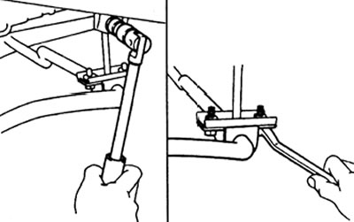
G) Remove the stabilizer bar on the other side in the same way.
Examination
Rotate the ball joint of the stabilizer link in all directions: the movement of the joint must be smooth and free. If not, replace the stabilizer link.
Installation
1. Installation of the stabilizer.
A) Install the stabilizer pads on the stabilizer, in the places defined by the painted lines. Install the mounting brackets.
b) Install the racks on the stabilizer and tighten the mounting bolts.
Tightening torque - 18 N.m
V) Connect the stabilizer links to the frame and temporarily tighten the mounting nuts.
G) Using brackets, connect the stabilizer to the front axle and temporarily secure with the fastening nuts.
2. Lower the vehicle and rock it up and down to stabilize the suspension.
3. Tighten the bolts securing the stabilizer to the front axle.
Tightening torque - 18 N.m
3. Tighten the nuts securing the stabilizer bar to the frame.
Tightening torque - 113 N.m