
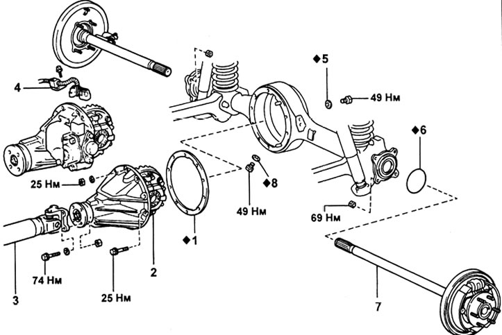
Reducer assembly. 1 - gasket, 2 - gearbox, 3 - rear propeller shaft, 4 - locking mechanism drive connectors, 5 - filler plug gasket, 6 - O-ring, 7 - axle shaft, 8 - drain plug gasket.
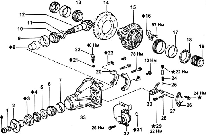
Reducer with differential lock mechanism. 1 - washer, 2 - pinion flange, 3 - boot, 4 - oil seal, 5 - flinger, 6 - front bearing, 7 - front bearing outer race, 8 - spacer sleeve, 9 - rear bearing outer race, 10 - rear bearing, 11 - washer, 12 - final drive gear, 13 - differential cup bearing, 14 - final drive driven gear, 15 - differential assembly, 16 - locking plate, 17 - bearing outer race, 18 - adjusting nut, 19 - coupling, 20 - bearing caps, 21 - gasket, 22 - lock-on sensor, 23 - lock plate, 24 - spring, 25 - ball, 26 - stem holder, 27 - fork stem, 28 - pin, 29 - plug, 30 - locking fork, 31 - sealing ring, 32 - locking mechanism drive, 33 - gearbox housing.
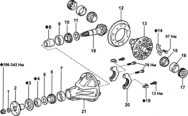
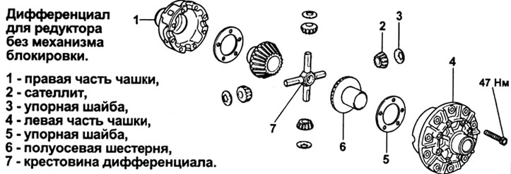
Reducer without differential lock mechanism. 1 - washer, 2 - pinion flange, 3 - boot, 4 - oil seal, 5 - flinger, 6 - front bearing, 7 - front bearing outer race, 8 - spacer sleeve, 9 - rear bearing outer race, 10 - rear bearing, 11 - washer, 12 - final drive gear, 13 - differential assembly, 14 - stop plate, 15 - differential cup bearing, 16 - bearing outer race, 17 - adjusting nut, 18 - final drive gear, 19 - locking plate, 20 - bearing caps, 21 - gearbox housing.
Replacing the front oil seal without removing the gearbox from the car
Note: for adjustment, removal and installation of parts when replacing the front oil seal, see subsection "Replacing the rear oil seal without removing the gearbox from the car" section "Front axle reducer".
1. Remove the rear driveshaft.
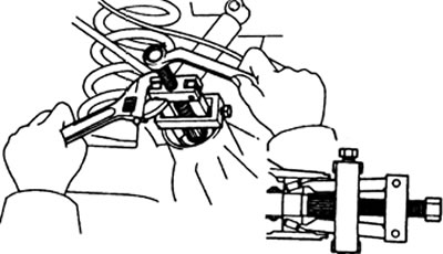
2. Remove the final drive gear flange.
3. Using a special tool, remove the oil seal, then remove the flinger ring.
4. Using the special tool, remove the drive gear front bearing.
5. Remove the bearing spacer.
6. Install a new spacer and bearing.
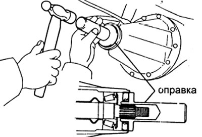
7. Install the flinger as shown in the illustration.
8. Using a drift and a hammer, install a new oil seal as shown.
Seal fitting depth — 1.0 mm
9. Apply grease to the seal lip.
10. Install the final drive gear flange.
11. Check pinion bearing preload.
Preload (elementary):
- new bearing - 1.0-1.6 N.m
- old bearing - 0.5-0.8 N.m
12. Caulk the pinion nut.
13. Connect the rear propeller shaft to the drive gear flange.
14. Check the oil level in the gearbox housing. Add oil if necessary.
Removing the gearbox
1. For models with a rear differential lock: perform preliminary operations (see the corresponding paragraph in the section "Rear differential lock drive").
2. Remove the drain plug and drain the oil from the gearbox housing.
3. Remove the axle shafts from the rear axle housing.
4. Disconnect the rear driveshaft.
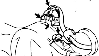
5. For models with a rear differential lock: Disconnect the connectors from the lock actuator.
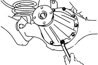
6. Turn away bolts and remove a reducer case.
Caution: Be careful not to damage the mounting surfaces.
Installing the gearbox
1. For models with a differential lock mechanism: check the operation of the lock mechanism.
A) Connect the lock actuator connector and check the operation of the mechanism depending on the position of the differential lock switch.
b) After checking, lock the rear differential.
2. Install a new gasket.
3. Install the gearbox housing on the rear axle and secure with two nuts and 10 bolts. Tighten nuts and mounting bolts.
Tightening torque - 25 Nm.
4. For models with a rear differential lock: Connect the connectors to the lock actuator.
Note:
- When connecting the breather tube from the wire bundle side to the hose of the locking mechanism, the depth of insertion of the tube into the hose must be 15 mm.
- The possibility of water penetration to the connector and hose must be excluded.
5. Connect the rear driveshaft to the drive gear flange.
6. Install the axle shafts in the rear axle housing.
7. Install drain plug.
8. Fill the hypoid gear oil into the gear case.
9. For models with differential lock:
- A) Checking the operation of the locking mechanism.
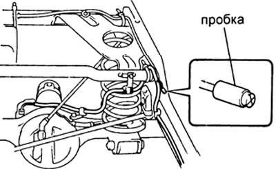
- b) Check that the plug in the area of the breather tube (above right side frame member) not damaged or worn.
Checking the gearbox
Note: check operations that are missing in this subsection, see the corresponding subsection of the section "Front axle reducer".
1. Checking the pinion preload.
Measure the preload provided by the gap between the teeth of the driven and driving gears.
Preload (elementary) — 0.5 - 0.8 N.m
2. Checking the total preload.
A) Measure the total preload.
Total preload: add 0.4-0.6 Nm to the pinion preload.
b) If necessary, disassemble and check the differential.
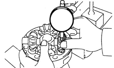
3. Checking the backlash in the engagement of the side gear.
A) Measure side gear backlash while holding the side gear and spider.
Permissible gap - 0.05-0.20 mm
b) If the side clearance is not within specifications, install a thrust washer of the correct thickness.
Thickness of thrust washers - 0.9; 1.0; 1.1; 1.2; 1.3mm