
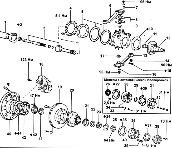
Steering knuckle and half shaft. 1 - front axle housing; 2 - stuffing box; 3 - axle shaft assembly; 4 - gland holder; 5 - set of stuffing box parts (felt boot; rubber seal; steel ring); 6 - upper arm of the steering knuckle; 7 - conical washer; 8 - adjusting gasket; 9 - upper bearing; 10 - gasket; 11 - bushing; 12 - axis of the steering knuckle; 13 - the lower arm of the steering knuckle; 14 - castellated nut; 15 - cotter pin; 16 - washer; 17 - lower bearing; 18 - caliper assembly; 19 - brake disc; 20 - hub; 21 - bearing; 22 - thrust washer; 23 - adjusting nut; 24 - lock washer; 25 - locknut; 26 - contact ring; 27 - gasket; 28 - clutch housing; 29 - retaining ring; 30 - gasket; 31 - coupling cover; 32, 33 - washer; 34 - conical washer; 35 - gasket; 36 - clutch housing; 37 - gasket; 38 - clutch cover; 39 - washer; 40 - conical washer; 41 - bearing; 42 - stuffing box; 43 - boot holder; 44 - gasket; 45 - protective cover of the brake disc.
Disassembly
1. Remove the wheel hub.
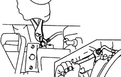
2. Using pliers, remove the clip. Disconnect the brake hose from the tube and bracket on the axle housing.
3. Turn away eight bolts of fastening of an axis of a rotary fist.
4. Remove the boot holder, gasket and protective cover.
5. For models with automatic clutch lock: Disconnect the clutch lock actuator connector.
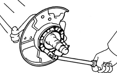
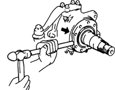
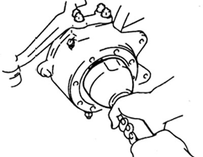
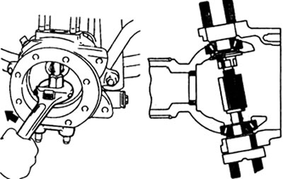
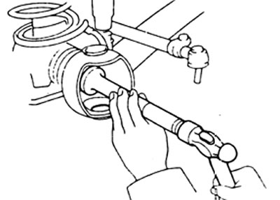
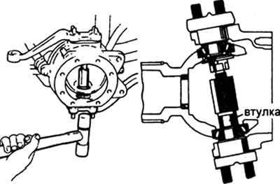
6. Using a brass drift and a hammer, remove the steering knuckle axle.
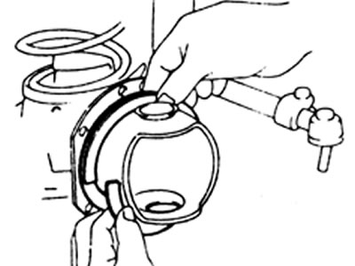
7. Position the flat side of the outside of the axle shaft up and remove the axle shaft assembly.
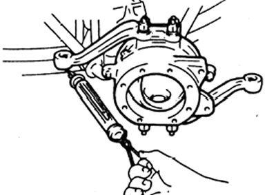
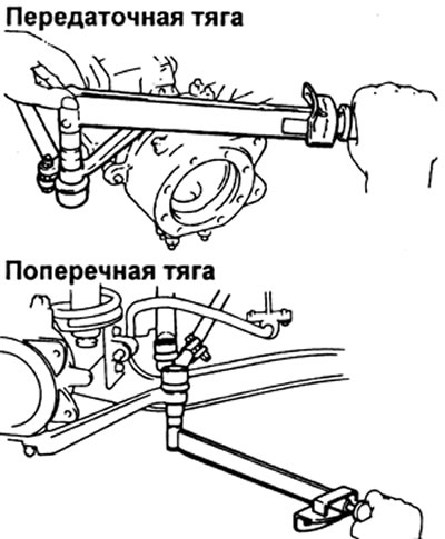
8. Remove cotter pins, turn away castellated nuts, then disconnect tips of steering draft from levers of a rotary fist.
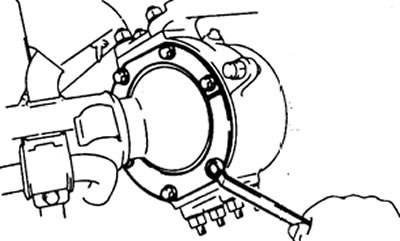
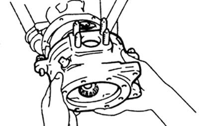
9. Turn away six bolts and remove the holder and details of an epiploon.
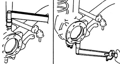
10. Removing the knuckle arm and bearing cap.
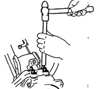
A) Turn away nuts of fastening of a rotary fist and a cover of the bearing.
b) Using a brass drift and hammer, remove the cone washers from the mounting bolts.
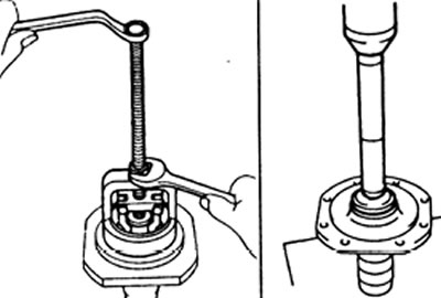
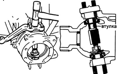
V) Using the special tool, push out the upper arm (or bearing cover) and shims from the steering knuckle.
Note: use the special tool without narrow bushing.
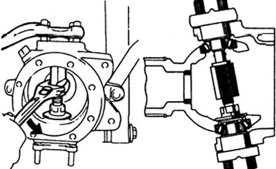
G) Similarly, using a special tool, disconnect the lower arm from the steering knuckle.
11. Remove a rotary fist and take bearings.
Note: Store the removed shims and bearings separately so as not to confuse them during assembly.
Check and repair
1. Checking the axis of the steering knuckle,
A) Wash the steering axle
b) Check the steering knuckle bushing for wear or damage.
2. Replacing the bushing axis of the steering knuckle.
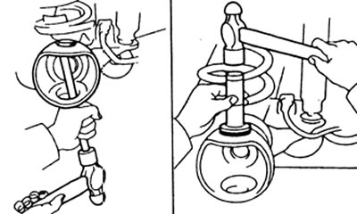
A) Using the special tool, remove the bushing from the axle.
b) Using the special tool, press a new bushing into the axle.
3. Checking the steering knuckle bearings.
A) Clean the bearings and their outer races.
b) Check bearings for wear or damage.
4. Replacing the bearing outer ring (if necessary).
A) Using a brass drift, knock out the bearing outer race.
b) Install a new bearing outer race using a special mandrel.
5. Checking the details of the axle shaft hinge.
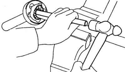
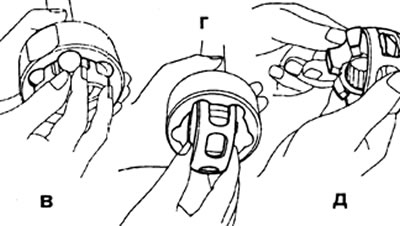
A) Clamp the inside of the axle shaft in a vise.
b) Install the brass rod on the inner race of the hinge and knock out the outer part of the axle shaft with hammer blows.
V) Tilt the inner race and pivot cage to the side and remove the balls.
G) Align the two large holes in the cage against the protrusions of the outer race, and remove the cage and inner race assembly.
d) Remove the inner race from the separator through the large opening.
e) Clean the hinge parts and check them for signs of wear or damage.
and) Lubricate the inner parts of the hinge and the inner surface of the outer race with a lithium-based lubricant with molybdenum disulfide.
h) Install the inner race into the separator through the large hole.
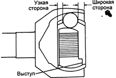
And) Install the inner race so that its protrusions are directed towards the wide part of the cage.
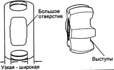
To) Assemble the cage and inner race to the outer race by positioning the two large holes against the tabs on the outer race.
l) Make sure the wide side of the cage and the tabs on the 'inner joint race' are facing out.
m) Set balls (see paragraph "V"),
n) Pack the outer race with lithium based molybdenum disulphide grease.
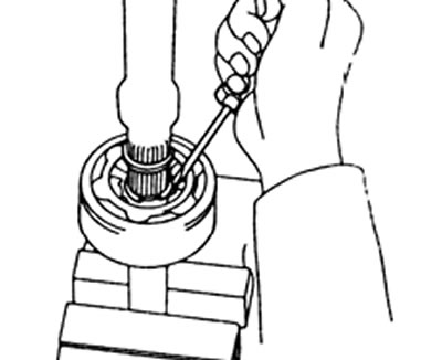
O) Install new circlips on the inside of the axle shaft.
P) Clamp the outer part of the axle shaft in a vise, compress the circlip and install the inner part of the axle shaft.
R) Make sure that the inside of the axle shaft is securely fixed.
6. Replacing the front axle oil seal.
A) Using a puller, remove the oil seal from the front axle housing.
b) Using a special mandrel, install the oil seal in the front axle housing.
Assembly
1. Install the felt boot, rubber seal and steel ring.
2. Packing of bearings with grease based on lithium and molybdenum disulphide.
A) Take some lithium-based lubricant with your finger.
b) Start packing grease into the bearing, and keep doing this until grease comes out the other side of the bearing.
V) Do this operation around the entire circumference of the bearing.
3. Install the lower bearing in the steering knuckle, and the upper bearing in the front axle housing.
4. Install the steering knuckle on the front axle housing.
5. Installing the knuckle arm and bearing cap.
A) Place the special tool against the inner race of the upper bearing.
Note: Use a special tool with a bushing.
b) Install the bearing cap or upper arm over the shims that have already been installed or selected according to the adjustment operations.
V) Lightly tap the bearing cap with a hammer (or upper steering arm), by inserting it into the inner ring of the bearing.
G) Use the special tool to support the lower bearing inner race.
d) Install the lower knuckle arm together with the shims that were already installed or selected according to the adjustment operations.
e) Lightly tap with a hammer to insert the lower steering knuckle arm into the bearing inner race.
and) Remove the special tool from the steering knuckle.
h) Install the cone washers, spring washers, and nuts securing the upper knuckle arm or bearing cap.
Tightening torque - 96 N.m
And) Install the cone washers, spring washers and lower knuckle arm mounting nuts.
Tightening torque - 96 N.m
6. Checking the preload of the axle shaft bearings.
A) Using a spring dynamometer, measure the bearing preload.
Preload 25 - 44 N
b) If the preload is not within acceptable limits, then adjust it by replacing the shims.
The thickness of the shims is 0.1; 0.2; 0.3; 0.5; 1.0 mm
Note:
- If the preload is too high, then increase the thickness of the shims, if too small, then reduce the thickness of the shims.
- When changing the total thickness of the gaskets by 0.1 mm, the preload will change by 1 - 2 N.
7. Connect steering drafts with levers of a rotary fist. Tighten castle nuts and secure with cotter pins.
Tightening torque - 91 N.m
8. Establish the holder and details of an epiploon on a rotary fist and tighten six bolts of fastening.
Tightening torque - 5.4 N.m
9. Position the flat side of the outside of the axle shaft up and install the axle shaft assembly.
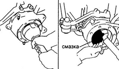
10. Pack lithium grease with the addition of molybdenum disulphide into the knuckle approximately 3/4 of its depth.
11. Install a new gasket on the steering knuckle, then install the steering knuckle axle.
Note: for models with automatic clutch lock:
- Be careful not to damage the wiring and rubber gasket when installing the knuckle shaft.
- Make sure the tape is completely removed from the knuckle pin.
12. Establish the holder of an anther, a lining and a protective casing on an axis of a rotary fist and tighten bolts of fastening.
Tightening torque - 47 N.m
13. For auto-lock models: Connect the clutch lock actuator connector.
14. Connect the brake hose to the tube and bracket on the axle housing, then use the pliers to install the clamp.
15. Install the wheel hub