
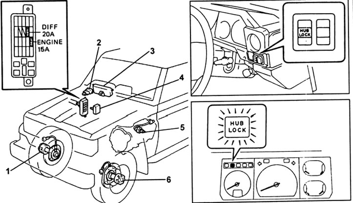
Freewheel locking system. 1 - right wheel clutch lock drive, 2 - switches (all-wheel drive control and clutch lock control), 3 - instrument cluster (clutch lock indicator, four-wheel drive indicator and speed sensor), 4 - four-wheel drive control unit (4WD), 5 - all-wheel drive enable sensor (4WD), 6 - drive for blocking the clutch of the left wheel.
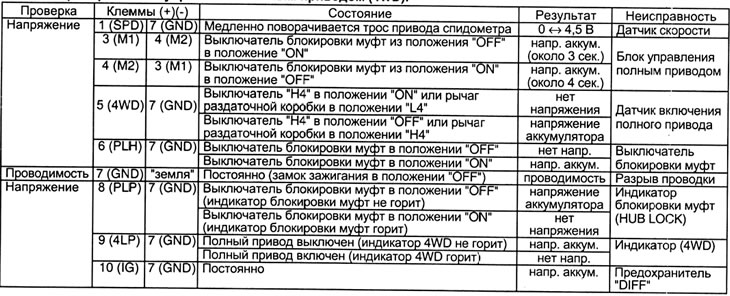
All-wheel drive control unit check table (4WD).
Checking system operation
1. Checking the indicator "HUB LOCK".
A) Set the ignition switch to position "ON" (Included).
b) Engage the clutch lock: the indicator should light up.
V) Switch off the clutch lock: the indicator should turn off.
2. Checking the operation of the freewheel lock.
A) Hang the front wheels of the car.
b) Set the ignition switch to position "ON" (Included).
V) Engage the clutch lock, check the condition of the indicator and freewheels.
Note:
- After setting the lock switch to position "ON" smoothly turn the front wheels to engage the clutch lock.
- To check clutch lock operation, disengage 4WD, rotate the front driveshaft and check that the left and right wheels turn.
d) Set the ignition switch to position "OFF" (Turned off).
e) Lower the car onto its wheels.
3. Checking the operation of the system.
A) Jack up the car and start the engine.
b) At a speed of 8 km/h or more, set the clutch lock switch to "ON" and check that the indicator "HUB LOCK" blinking.
V) Turn on all-wheel drive (press the button "H4").
G) Make sure the indicator "HUB LOCK" lights up, then turn off the four-wheel drive (button "H4").
d) At a speed of 5 km/h or less, check that the clutch lock indicator is on.
e) Stop the engine and lower the car onto its wheels.
Checking the elements of the control system
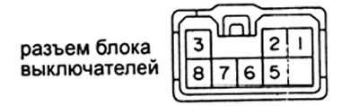
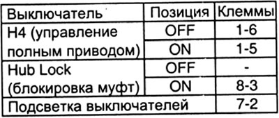
1. Checking the four-wheel drive control switches (H4) and locking freewheels.
Check the switch according to the table. Replace the switch if the conductivity is not as specified.
2. Checking the all-wheel drive enable sensor (4WD).
A) Remove the sensor from the transfer case.
b) Check for continuity between terminals 1 and 2 of the sensor connector when the ball is depressed.

V) Check for continuity between terminals 1 and 2 of the sensor connector when the ball is released.
5. Checking the speed sensor (in the instrument cluster).
A) Remove the instrument cluster.
b) Use a screwdriver to turn the speedometer shaft.
Note: Tape the end of the screwdriver before use.
V) Make sure that between the terminals "A" And "IN" conduction occurs four times per revolution of the shaft. Replace the speed sensor if it does not work as specified.
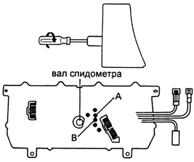
G) Install the instrument cluster.
4. Checking the clutch lock indicator (HUB LOCK).
A) Remove the instrument cluster.
b) Connect the battery to terminals 3 (+) and 4 (-) connector.
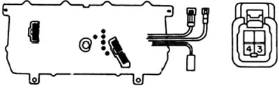
V) Check that the indicator lights up. If the indicator does not light up, then check the indicator lamp.
G) Install the instrument cluster.
4. Checking the four-wheel drive indicator (4WD).
A) Remove the instrument cluster.
b) Connect the battery to terminals A7 (+) and B7 (-). Check that the indicator lights up. If the indicator does not light up, then check the indicator lamp.
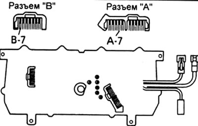
V) Install the instrument cluster.
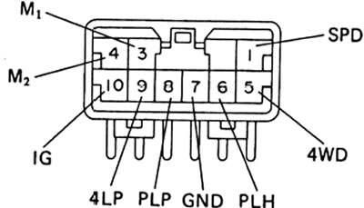
5. Checking the four-wheel drive control unit (4WD).
A) Make sure the battery voltage is correct.
b) Check the control unit with the plug connected according to the table.
Note: check with the power on "ignition".
Checking the clutch lock actuator
1. Checking the operation of the clutch lock drive.
A) Disengage 4WD and Install Clutch Lockout Switch (HUB LOCK) into position "ON".
b) Raise the front of the car and block the rear wheels.
V) Disconnect the connector from the disc brake guard.
G) Check that the wheel couplings are locked.
d) Connect the battery to terminals 1 (+) and 2 (-) lock motor connector. Check that the drive is working and the clutch is out of position "LOCK" goes into position "FREE".
Attention: the duration of connecting the battery to the connector terminals should not exceed 4 seconds.
Note: To check the disengagement of the clutch lock, turn the front propeller shaft and make sure that the left and right wheels do not turn.
e) Reverse the polarity of the battery connection and check that the drive works, the clutch is out of position "FREE" goes into position "LOCK".
Note: If at least one of the clutches is not locked, then the left and right wheels will not rotate when the front propeller shaft is rotated.
and) Connect the connector, and lower the car on the wheels.
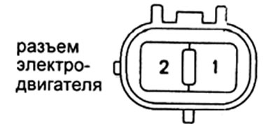
2. Checking the electric motors of the clutch lock drive.
A) Disconnect the connector from the disc brake guard.
b) Measure the resistance between the motor connector terminals. If the resistance is out of range, check the freewheel housing.
Resistance - 20 - 500 Ohm
V) Check for continuity between each motor connector terminal and "earth". Replace the clutch housing if there is continuity between the terminals.
G) Connect the connector.