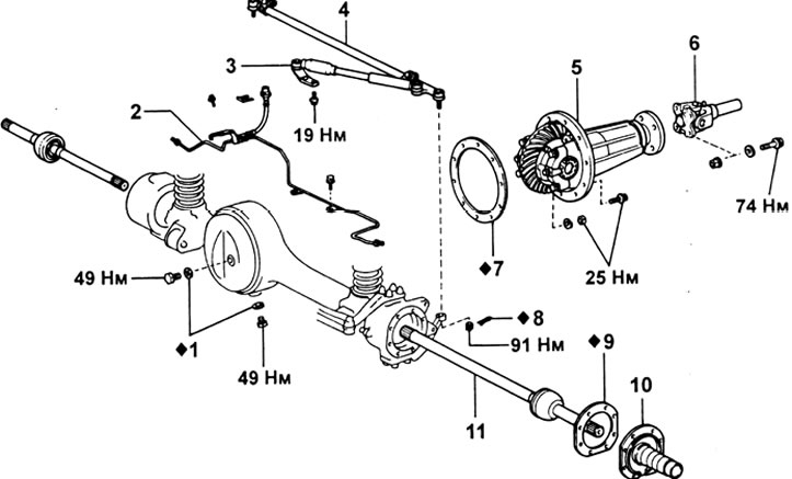
Reducer assembly. 1 - gasket; 2 - tubes of the brake system; 3 - steering damper; 4 - transverse steering rod; 5 - reducer; 6 - front propeller shaft; 7 - gasket; 8 - cotter pin; 9 - gasket; 10 - axis of the steering knuckle; 11 - axle shaft assembly.
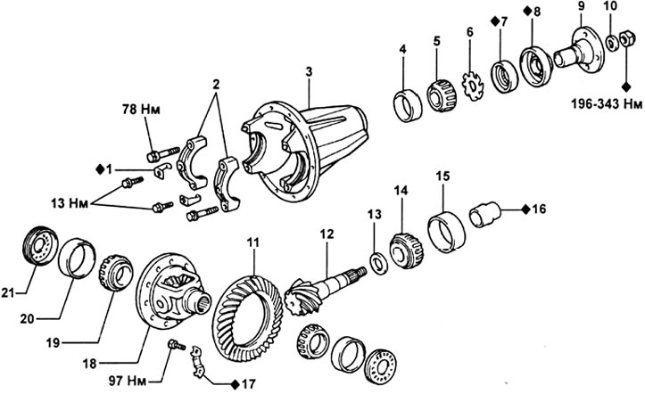
Reducer. 1 - locking plates; 2 - bearing caps; 3 - reducer harter; 4 - outer race of the front bearing; 5 - front bearing; 6 - oil flinger ring; 7 - stuffing box; 8 - anther; 9 - drive gear flange; 10 - washer; 11 - driven gear; 12 - drive gear; 13 - washer; 14 - rear bearing; 15 - outer race of the rear bearing; 16 - spacer sleeve; 17 - locking plate; 18 - differential cup; 19 - differential cup bearing; 20 - outer race of the differential cup bearing; 21 - differential cup bearing adjusting nut.
Replacing the rear oil seal without removing the gearbox from the car
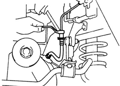
1. Removing the front driveshaft.
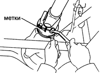
A) Mark the front propshaft flange and final drive gear flange.
b) Turn away four bolts and nuts and disconnect a forward propeller shaft.
2. Removing the main gear drive flange.
A) Using a chisel and hammer, loosen the caulked portion of the flange mounting nut.
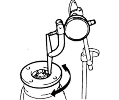
b) While holding the flange with the special tool, remove the nut and plate washer.
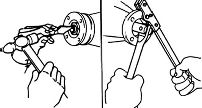
V) Using the special tool, remove the connecting flange.
3. Using a special tool, remove the oil seal, then remove the flinger ring.
4. Using the special tool, remove the pinion rear bearing.
5. Remove the bearing spacer.
6. Install a new bearing spacer.
7. Install the rear bearing.
8. Installation of a flinger ring and a new stuffing box.
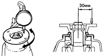
A) Install the flinger ring as shown in the illustration.
b) Install a new oil seal using the special tool as shown.
Seal fitting depth — 1.0 mm
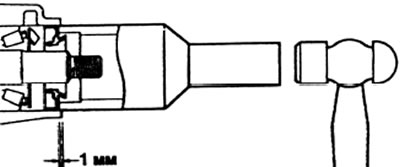
V) Apply grease to the seal lip.
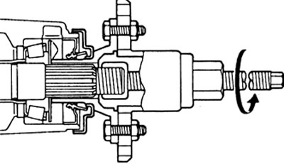
9. Installing the main gear drive flange.
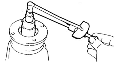
A) Using the special tool, install the flange onto the drive gear.
b) Install the flat washer on the flange.
V) Apply a small amount of gear oil to the threads of the new flange nut.
G) While holding the flange, tighten the nut.
Tightening torque - 196 N.m
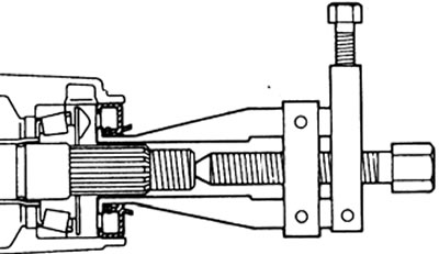
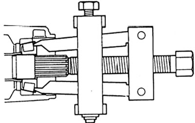
10. Checking the preload of the pinion bearings.
A) Using a torque wrench, measure the preload.
Preload (elementary):
- new bearing - 1.9 - 2.5 N.m
- old bearing - 0.9-1.3 N.m
b) If the preload is greater than specified, replace the spacer sleeve.
V) If the preload is less than the specified, then re-tighten the nut with a torque of 13 Nm more than the nominal (196 N.m) until the set preload is reached.
G) If the torque limit is exceeded when tightening the nut, the bearing spacer must be replaced and the procedure repeated.
Tightening torque limit - 343 N.m
Caution: Do not loosen the nut to reduce the preload.
11. Caulk the pinion nut.
12. Align the marks and connect the main gear drive flange with the propeller shaft flange. Secure the flanges with bolts, spring washers and nuts. Tighten bolts and nuts.
Tightening torque - 74 N.m
13. Check the oil level in the gearbox housing. Add oil if necessary.
Removing the gearbox
1. Remove the drain plug and drain the oil from the gearbox housing.
2. Remove the half shaft assembly from the front axle housing.
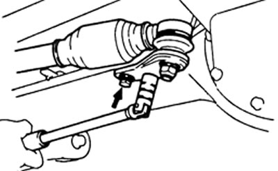
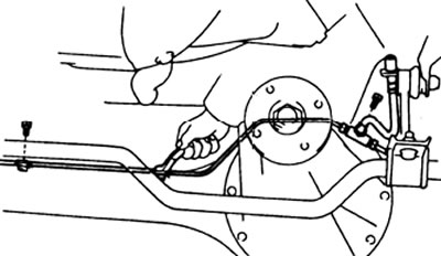
3. Removing the tie rod.
A) Using the special tool, disconnect the tie rod from the lower steering knuckle arm.
b) Remove the two steering damper bracket bolts.
4. Disconnect the front propeller shaft.
5. Removing the tubes of the brake system.
A) Disconnect the tube from the side of the frame and remove the clip.
b) Turn away bolts of fastening of clips and remove a tee in gathering with a hose and tubes.
6. Turn away bolts and remove a reducer case.
Attention: be careful not to damage the mounting surfaces.
Installing the gearbox
1. Install a new gasket.
2. Install the gearbox housing on the front axle and tighten the two nuts and eight mounting bolts.
Tightening torque - 27 N.m
3. Installation of tubes of the brake system.
A) Install the tee assembly with hose and tubes. Tighten the clamp mounting bolts.
b) Connect the tube from the side of the frame and install the clamp.
4. Connect the front propeller shaft.
5. Installing the tie rod,
A) Install the steering damper bracket and tighten the two mounting bolts.
Tightening torque - 19 N.m
b) Connect the tie rod to the lower steering knuckle arm. Tighten the castle nut and install the cotter pin.
Tightening torque - 91 N.m
6. Establish half shafts in gathering.
7. Install drain plug.
8. Fill the gear case with gear oil.
Checking the gearbox
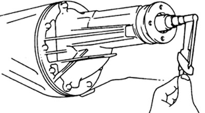
1. Checking the runout of the final drive gear flange.
A) Using a dial indicator, measure the axial runout of the flange.
Maximum axial runout - 0.10 mm
b) Using a dial indicator, measure the radial runout of the flange.
Maximum radial runout - 0.10 mm
2. Checking the runout of the driven gear of the final drive.
A) Measure the runout of the driven gear.
Maximum runout - 0.10 mm
b) If the runout exceeds the maximum value, then replace the final drive gear.
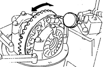
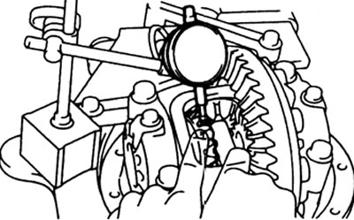
3. Checking the backlash between the teeth of the driven and driving gears.
A) Mount the indicator on the tooth surface at a 90°angle.
b) While holding the drive gear flange, measure the backlash between the driven and drive gears.
Lateral clearance between the teeth of the driven and driving gears - 0.13-0.18 mm
Note: Take measurements at three or more points on the periphery of the driven gear.
V) If the side clearance is not within the specified range, adjust the side bearing preload or repair if necessary.
4. Checking the pinion preload.
Measure the preload provided by the gap between the teeth of the driven and driving gears.
Preload (elementary) — 0.9 -1.3 N.m
5. Checking the total preload.
A) Measure the total preload.
Total preload: add 0.4-0.6 Nm to the pinion preload.
b) If necessary, disassemble and check the differential.
6. Checking the backlash in the gearing of the side gear.
A) Measure the backlash between the teeth on the side gear by pressing one of the satellites against the differential cup.
Permissible gap - 0.05 - 0.20 mm
b) If the gap value is out of range, then thrust washers of the appropriate size should be installed.
Thickness of thrust washers - 1.6; 1.7; 1.8mm
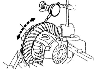
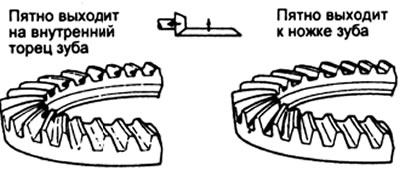
7. Checking the contact patch between the teeth of the driving and driven gears.
A) Apply red paint to 3-4 teeth of the driven gear in three different places.
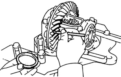
b) While holding the drive gear flange, turn the driven gear in both directions.
V) Check the shape of the contact patch between the gear teeth.
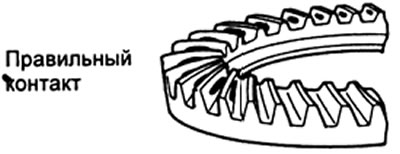
G) If the drive gear is too far from the center of the driven gear, increase the thickness of the shim to bring the driven gear and drive gear closer together, or move the driven gear away from the drive gear to adjust the backlash.
Thickness of adjusting washers - 1.70 - 2.33 mm (with a step of 0.03 mm)
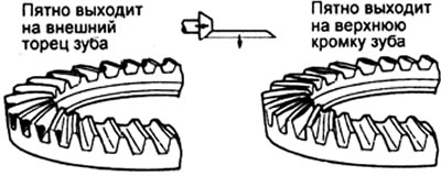
d) If the drive gear is too close to the center of the driven gear, thin the shim to move the driven gear away from the drive gear, or move the driven gear closer to the drive gear to adjust the backlash.
8. Checking the runout of the differential cup.
Using a dial indicator, measure differential cup runout.
Maximum runout - 0.07 mm