



- Check the crankshaft for damage and measure the journals of the main and connecting rod bearings. Measure the taper and ovality in the directions shown in Figure 100. To install a crankshaft with oversized bearing shells, the main bearing journals and connecting rod journals can be turned.
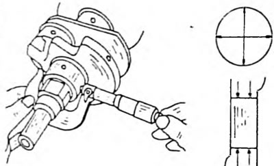
Fig. 100. Measuring the diameter of the crank pin. Measure at the specified location.
- Clamp the crankshaft in the lathe centres (or insert it with both outermost journals into the prisms) and check the runout of the middle bearing journal using a dial indicator. The runout should not exceed 0.06 mm per full revolution (Fig. 101). Otherwise, replace the shaft.
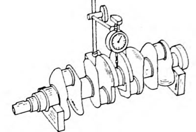
Fig. 101. Checking the crankshaft runout on the middle main journal.
- Measure the clearances of the main and connecting rod bearings:
— Clean the bearing shells and place them in the bearing beds of the cylinder block or in the connecting rods.
— Place a piece of PLASTIGAGE plastic hair on all main journals as shown in Figure 102 and place the main bearing caps with inserted liners. Tighten the bolts to a tightening torque of 60 Nm. After this, the shaft must not be turned.
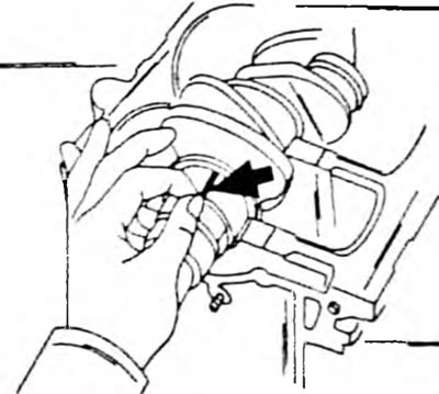
Fig. 102. Applying PLASTIGAGE hair to crankshaft journals.
— To check the play of the connecting rod bearings, place the connecting rods on the connecting rod journals and place a piece of PLASTIGAGE plastic hair on the upper side of the connecting rod journal. Install the bearing cap with the liner and tighten the nuts with a tightening torque of 50 Nm. Since the shaft cannot be turned, two connecting rod bearings located at the bottom dead center are taken. If the shaft is removed for inspection, position the connecting rods so that they cannot turn themselves after tightening.
— Install the main bearing caps; on the connecting rod bearings, unscrew both covers in sequence.
— Measure the widest point of the crushed hair using the supplied PLASTIGAGE template (Fig. 103). The clearance is normal if it is within the values specified in the table of sizes and adjustments for main and connecting rod bearings. If the wear limit is exceeded, new liners should be installed, and it should be taken into account whether the journals have already been turned, since there is only one repair size.
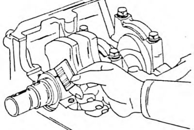
Fig. 103. Measuring the width of the crushed PLASTIGAGE hair when determining bearing play.
— If the connecting rod bearing play is being checked, rotate the crankshaft and measure the other connecting rod journals as described above.
- When selecting a new bearing, the following guidelines should be considered:
— If the main bearing clearances do not correspond to the specified values, check the numbering on the cylinder block. The number is stamped next to the corresponding main bearing and also characterizes the bearing size with the numbers 1, 2 or 3. The same number is stamped on the rear surface of each bearing shell. There are five different sizes of shells available. Identify each bearing by its number. Always take a bearing with the same number for replacement. If in doubt, contact a workshop.
The article is taken from a web resource ToyotaMan