
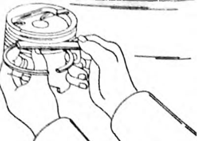
Pic. 91. Measuring the backlash along the height of the piston rings in the piston grooves. All valves must be well cleaned
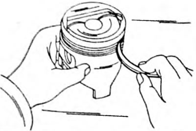
Pic. 92. Removing carbon deposits from piston ring grooves using a broken piston ring
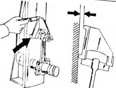
Next, insert all the piston rings one by one into the cylinders from the bottom side of the crankcase. Using the reverse side of the piston, insert the rings in accordance with Figure 93 into the cylinders. In this case, they sit directly in the cylinder bore. Should be considered. that the wear criteria for 1.6 l and 2.0 l engines are different, that is, the specified immersion depth must be observed. To measure the thermal clearance of the piston ring lock, insert a feeler gauge into the ring lock, as shown in Figure 94. If the size exceeds the data given in the size and adjustment table, replace the piston rings. It should be taken into account that the thermal gap is not the same for all rings and for all engines.
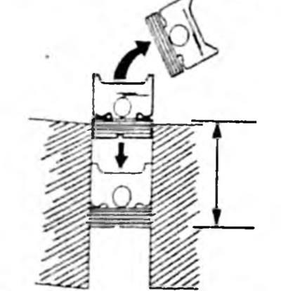
Pic. 93. Measuring the thermal clearance of the piston ring lock in the cylinder. Pull the inverted piston to depth (between the arrows) 110 mm on a 2.0 l engine or 87 mm on a 1.6 l engine.
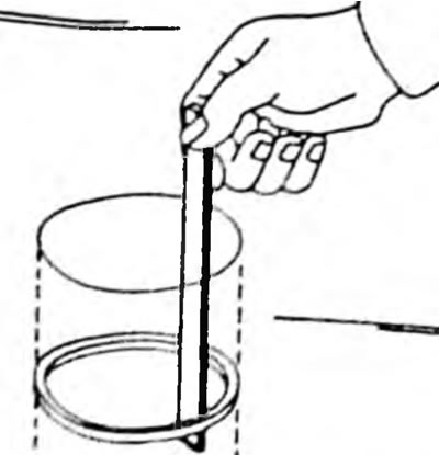
Pic. 94. Measuring the thermal gap of the piston ring lock
Check for wear or scoring on the piston pins. If only one connecting rod is rejected, the entire set should be replaced. The connecting rod bearing nuts must be replaced. Also check the bending and twisting of the connecting rods using a special installation (see fig. 95), which should be minimal, that is, over a length of 100 mm they can be bent by no more than 0.05 mm. Internal twist is allowed 0.15mm per 100mm on the 2.0L engine and 0.05mm per 100mm on the 1.6L engine. The connecting rod head bushings cannot be replaced.
Pic. 95. Connecting rods are checked for bending and torsion on a straightening machine. The bend test is shown here. When checking twisting, the probe is placed in the place indicated by the arrows.