
- Wipe the bearing beds and insert the bearing shells with their protrusions into the slots of the bearings. Lubricate the liners well, but make sure that the oil does not come out.
- Place the thrust half-rings at the middle main bearing. The lubrication grooves face the crankshaft flange, that is, outward, as can be clearly seen in Figure 105.
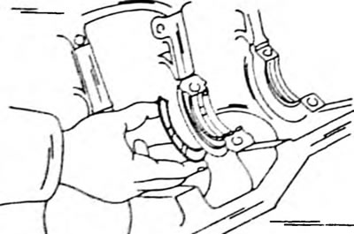
Pic. 105. Place thrust half-rings into the cylinder block with the lubrication grooves facing outwards. Similarly, the half rings are placed in relation to the main bearing caps, but are brought out beyond the protrusion.
- Carefully insert the crankshaft into the bearing shells. If the connecting rods are still in the cylinder block, install the connecting rod bearings onto the connecting rod journals.
- Place the lower shells in the crankshaft bearing cover (protrusions into cutouts) and lubricate the surfaces well.
- Put the covers on and tap them with a new or plastic hammer. The arrows on all covers should point forward.
- Tighten the cover bolts from the center outwards in several passes to a tightening torque of 60 Nm. After tightening the bolts, turn the crankshaft several times to determine whether it may be jammed. To do this, a crankshaft pulley with a key is temporarily put on.
- Check the axial play again, as already described in chapter 2.7.2 (see also fig. 104). If the play was large from the very beginning, replace the thrust half-ring.
- Install pistons and connecting rods as described in chapter 2.6.4.
- Install both seals (chapters 2.7.4).
- Screw on the rear engine intermediate plate.
- Install the crankshaft sprocket with key and install the guide disc for the timing belt.
- Install the flywheel. On a 2.L engine, apply one or two drops of locking agent to the threads. On a 1.L engine this is not required, but it won't hurt if it is done. Hold the crankshaft by inserting a wooden wedge between the crank jaw and the crankcase wall, and tighten the bolts to the specified torque. If an automatic transmission is installed, install the driven disk in the same way. IN Chapter 2.7.5 Further instructions regarding the flywheel are given.
- Install the clutch onto the flywheel following the markings. The driven disk must be well centered (chapter 8.2). Tighten the bolts evenly crosswise to a tightening torque of 15-22 Nm.
- Install the oil pump (see chapter 3.2)
- Install oil pan (see chapter 3.1).
- Carry out all other work in reverse order.
- Finally, install the cylinder head and gas distribution mechanism as described in the relevant chapters.