
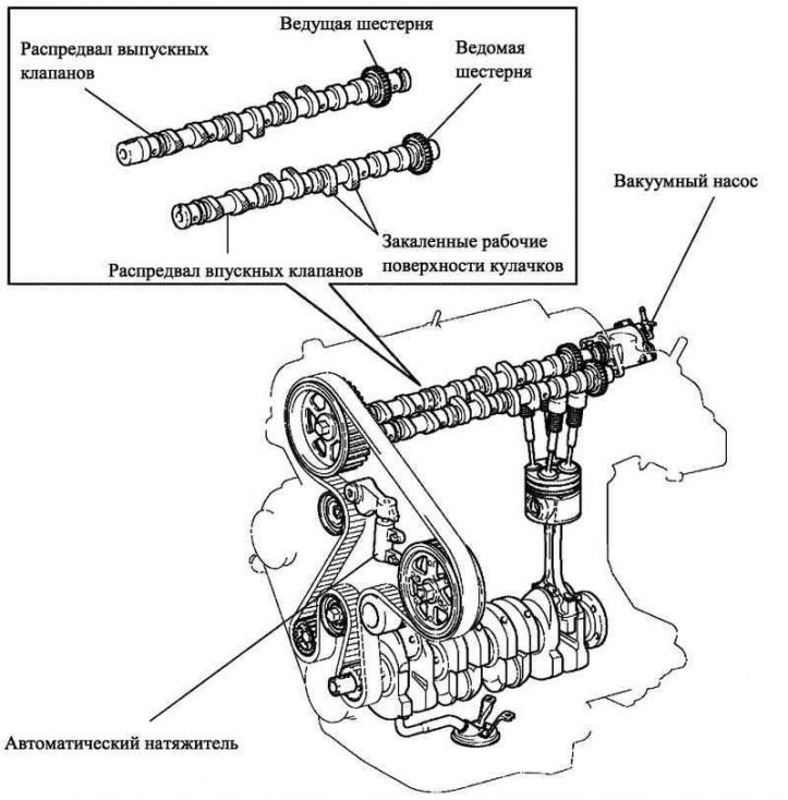
Pic. 2.67. 1CD-FTV engine valve train
The flow resistance in the intake and exhaust systems is reduced by increasing the total cross-sectional area of the channels.
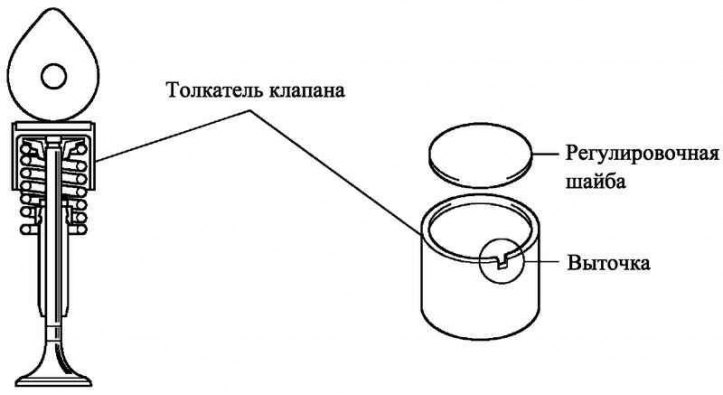
External adjusting washers are installed on the valve lifters.
The vacuum pump is driven by the exhaust camshaft.
The exhaust camshaft is driven by a belt driven valve train, and the intake camshaft is driven by a gear train from the exhaust camshaft.
Small diameter spur gears are used to drive the intake camshaft to reduce gear noise.
To increase wear resistance, the working surfaces of the cams are hardened.
The valve train drive belt is equipped with an automatic tensioner.
Inlet and outlet valves
Pic. 2.68. Inlet and outlet valves
This design allows shims to be replaced without removing the camshaft, making valve clearance adjustment easier.
To simplify the replacement of shims, a recess is provided in the valve lifter.
Maintenance recommendation
Shims are available in 17 sizes in 0.050 mm increments, from 2.50 mm to 3.30 mm.
Belt driven valve train
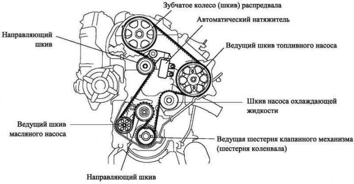
Pic. 2.69. Belt driven valve train
The tensioner reduces the noise generated by the timing belt.
Lubrication system
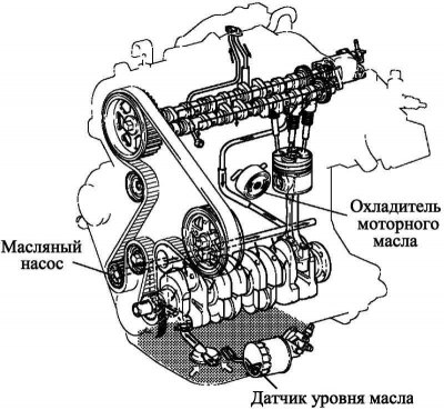
Pic. 2.70. 1CD-FTV engine lubrication circuit
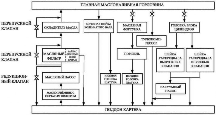
Pic. 2.71. Block diagram of the 1CD-FTV engine lubrication system
The lubrication system is sealed, the oil passes through a full-flow oil filter.
The pressure in the engine lubrication system is created by a trochoidal gear pump, which is driven by a valve belt.
To reduce the temperature of the engine oil, a liquid cooler is included in the lubrication system.
Oil jets are provided to cool the piston.
For ease of maintenance of the engine lubrication system, there is an oil level sensor in the oil pan.
Differences from previous models
To ensure maintainability, technological holes are provided in the engine protective cover for changing engine oil and oil filter.