
Adjustment
Disconnect the negative battery terminal.
Note. Before removing the high pressure fuel pipes, clean them with a soft brush and compressed air.
Note. After removing the high pressure fuel pipes, to prevent dust from entering, cover the injection pump, common rail fuel line and injectors with tape and secure it with vinyl tape.
Note. After removing the cylinder head cover, cover the intake ports of the injectors with a vinyl or plastic bag to prevent foreign particles from getting inside.
Attention! Check and adjust valve clearances after the engine has cooled down.
Remove the top outer hood panel.
Pic. 2.325. Fastening of the top casing of a radiator
Remove 6 clips, then remove the upper radiator shroud (pic. 2.325).
Remove the front right wheel.
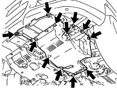
Pic. 2.326. Fastening of the lower left guard of the engine
Remove 4 bolts and 8 clips, then remove the lower left engine shield (pic. 2.326).
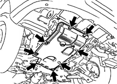
Pic. 2.327. Fastening of the bottom guard of the engine No. 1
Remove 2 bolts and 6 clips, then remove #1 engine bottom shield (pic. 2.327).
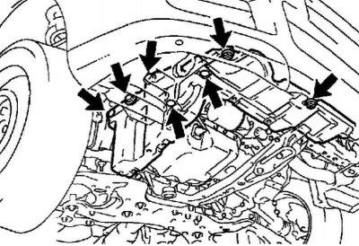
Pic. 2.328. Mounting the bottom shield of the engine
Unscrew 4 bolts and remove 3 clips, then remove the engine bottom shield (pic. 2.328).
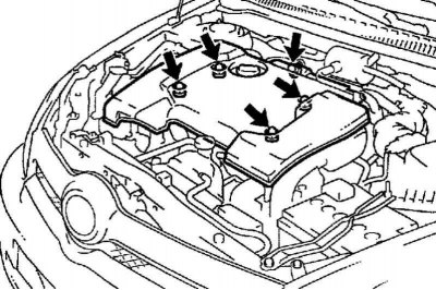
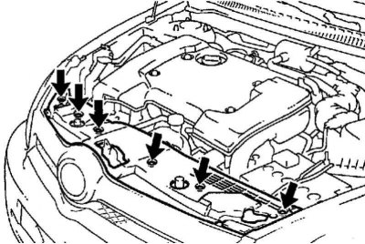
Pic. 2.329. Engine cover mount
Remove 5 nuts, then remove the engine cover (pic. 2.329).
Remove the battery.
Remove air duct no. 1.
Disconnect the engine wiring harness.
Remove timing belt cover #2.
Removing the high pressure fuel pipe No. 1
Remove the 2 nuts and disconnect the 2 upper retainers for the high pressure fuel pipes from the intake manifold.
Using SST, disconnect the high pressure fuel pipe from the common rail fuel rail.
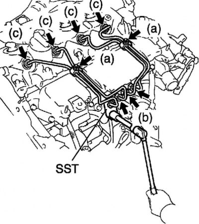
Pic. 2.330. Removing the high pressure fuel pipe No. 1
Using SST, disconnect the high pressure fuel line from the injector (pic. 2.330).
After removing the high pressure fuel pipe, cover the fuel rail with vinyl tape and cover the injector inlet with a plastic bag to keep out dirt and foreign particles.
Remove high pressure fuel lines #2 and #4.
Note. Perform the same operations as when removing the No. 1 high pressure fuel pipe.
Remove the cylinder head cover.
Remove the fuel return line assembly.
Remove the complete injectors.
Note. Since each injector has its own fuel injection characteristics, the removed injectors must be arranged in a certain order so that the injectors are reinstalled in their original positions during reassembly.
Valve clearance check
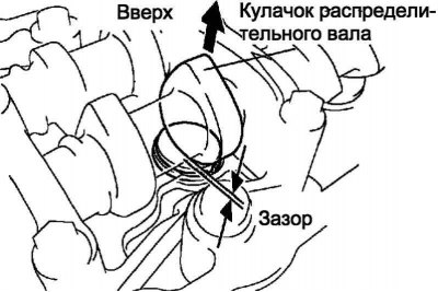
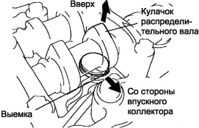
Pic. 2.331. Camshaft lobe position
Rotate the crankshaft so that the lobe of the cam located above the valve to be checked points up (pic. 2.331).
Using a set of feeler gauges, measure the clearance between the valve lifter and the camshaft cam.
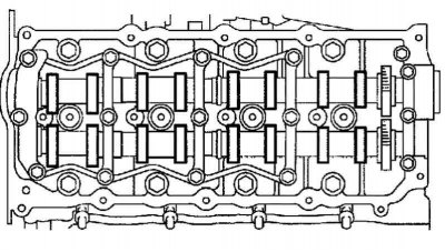
Pic. 2.332. Checked valves
Measure clearance in drive 16 valves (pic. 2.332)
Record valve clearance measurements that do not correspond to the prescribed values. In the future, these data will be required to select shims.
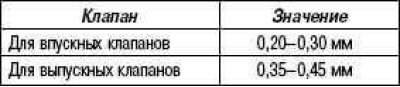
Valve clearance (cold engine)
Valve clearance adjustment
Remove the adjusting washer.
Turn the crankshaft so that the lobe of the cam located above the adjustable valve points up.
Pic. 2.333. Notch on the valve lifter
Turn the notch on the valve lifter towards the intake manifold (pic. 2.333).
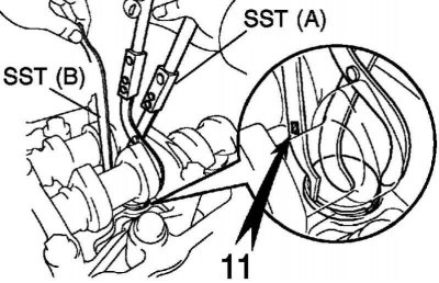
Pic. 2.334. Installation of special tools A and B
With SST (A) press the valve lifter down, then insert the SST (B) between the camshaft cam and the valve lifter. Remove SST (A) (pic. 2.334).
Note. Use SST (IN) with marking «11».
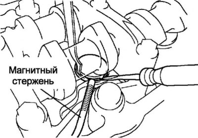
Pic. 2.335. Removing the shim
Using a small screwdriver and a magnetic bar, pry out the shim (pic. 2.335).
Select the replacement shim according to the formulas and tables at the end of this chapter.
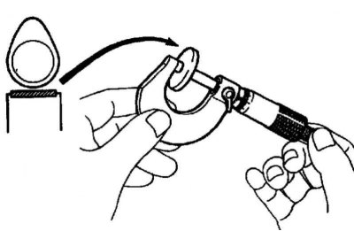
Pic. 2.336. Measuring the thickness of the removed washer
Measure the thickness of the removed washer with a micrometer (pic. 2.336).
Calculate the thickness of the new washer so that the valve actuator clearance is within the prescribed value.
- T - The thickness of the removed shim.
- A - Measured clearance in the valve actuator.
- N - Thickness of the new shim.
For intake valves:
N = T + (A–0.25 mm)
For exhaust valves:
N = T + (A–0.40 mm)
Note. Select a new washer that is closest in thickness to the calculated value.
Example (for intake valves)
Measured intake valve clearance = 0.45 mm.
0.45 mm - 0.25 mm = 0.20 mm.
(measured - nominal = excess clearance).
Measured washer thickness removed = 2.80 mm.
0.20 mm +2.80 mm = 3.00 mm.
(excess clearance + removed washer thickness = ideal new washer thickness)
Next new washer thickness = 3.00 mm.
Select washer #21.
Note. Shims are available in 17 sizes in 0.05 mm increments, from 2.50 mm to 3.30 mm.
Install a new shim.
Place a new shim on the valve lifter.
With SST (A) press the valve lifter down, then remove the SST (B) (pic. 2.334).
Recheck the clearance in the valve actuator.
Install the nozzle assembly.
Install the fuel return line assembly.
Install the cylinder head cover.
Install the #1 high pressure fuel pipe.
Note. Tubing should be installed with the engine at or below room temperature.
Remove the plastic bag from the injector and the vinyl tape from the fuel rail.
Install the high pressure fuel line.
Using SST, tighten the nut securing the high pressure fuel pipe to the fuel rail.
Tightening torque: 31 Nm with SST, 34 Nm without SST.
Note. Use a torque wrench with a lever length of 30 cm.
Note. After installation, make sure that the high pressure fuel pipe is not deformed and installed correctly. If the tube is deformed or cannot be installed correctly, replace the tube with a new one.
Using SST 09023-12700, tighten the nut securing the high pressure fuel pipe to the injector.
Torque: Used tubing 42 Nm with SST, 46 Nm without SST.
For new tubing: 31 Nm with SST, 34 Nm without SST.
Install the 2 upper high pressure fuel line retainers and secure with 2 nuts.
Tightening torque: 5.0 Nm.
Note. Install other components in the reverse order of removal.