
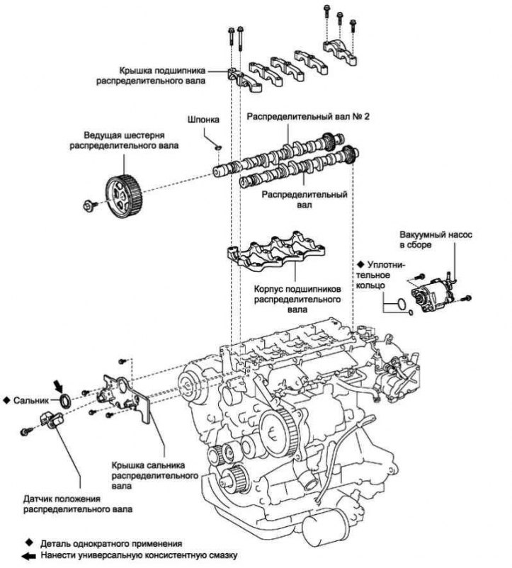
Pic. 2.364. Camshaft components
Removing the camshaft drive gear
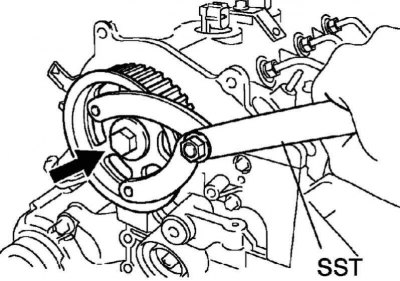
Pic. 2.365. Loosen gear bolt
Using SST, remove the pinion bolt (pic. 2.365).
Remove the camshaft drive gear.
Note. Remove the gear by lightly tapping it with a plastic mallet and remove the key.
Remove the high pressure fuel lines.
Remove the vacuum pump assembly.
Removing the nozzle body seal
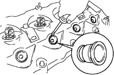
Pic. 2.366. Removing the nozzle body seals
Use a screwdriver to remove the 4 injector body seals (pic. 2.366).
Removing the cylinder head cover
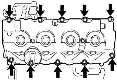
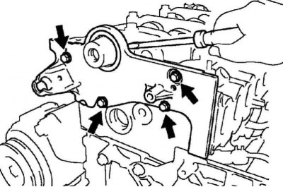
Pic. 2.367. Bolts of fastening of a cover of a head of the block of cylinders
Turn out 10 bolts of fastening, remove a cover of a head of the block of cylinders and a lining (pic. 2.367).
Remove the fuel return line assembly.
Remove the complete injectors.
Note. Since each injector has its own fuel injection characteristics, the removed injectors must be arranged in a certain order so that the injectors are reinstalled in their original positions during reassembly.
Removing the camshaft oil seal
Turn out 4 bolts of fastening.
Pic. 2.368. Removing the camshaft oil seal
Separate the oil seal cover by inserting a screwdriver between the oil seal cover and the camshaft bearing cover (pic. 2.368).
Removing camshafts
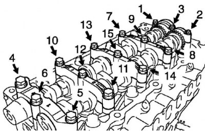
Pic. 2.369. The sequence of unscrewing the bolts of the bearing caps
In several steps, evenly, loosen and unscrew the 15 bolts of the bearing caps, acting in the sequence shown in Figure 2.369.
Remove 5 bearing caps and camshaft.
Remove the #2 camshaft and camshaft bearing housing.
Extraction of an epiploon of a camshaft
Pic. 2.370. Removing the camshaft seal
Remove the seal using a screwdriver and hammer (pic. 2.370).
Installing the camshaft oil seal
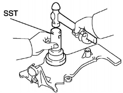
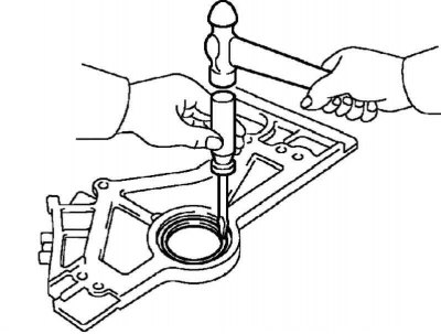
Pic. 2.371. Pressing in the camshaft seal
Using an SST tool and a hammer, press in the new oil seal until its surface is flush with the edge of the oil seal (pic. 2.371).
Apply multipurpose grease to the edge of the new oil seal.
Note. The seating surface of the seal must be free of sand, dirt and other foreign particles.
Installing the piston of cylinder No. 1 at TDC of the compression stroke
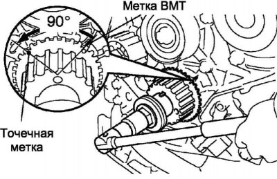
Pic. 2.372. Setting the piston of cylinder No. 1 to TDC of the compression stroke
Turn the crankshaft by the pulley mounting bolt and install the timing gear so that the dot mark on it takes the position of 90°to TDC, as shown in Figure 2.372.
Note. If you install the timing gear at a different angle, the piston crown may come into contact with the valve disc.
Installing the camshaft
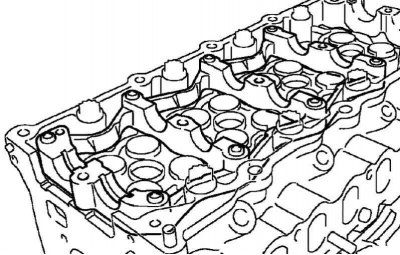
Pic. 2.373. Installing the camshaft bearing housing in the cylinder head
Install the camshaft bearing housing into the cylinder head (pic. 2.373).
Note. Due to the small axial clearance of the camshaft, the camshaft must be held strictly horizontal during assembly. If the camshaft is not horizontal, the cylinder head or camshaft may be damaged. To avoid this, follow the steps below.
Install the camshaft.
Lubricate the camshaft cams and camshaft gear and camshaft bearings with engine oil.
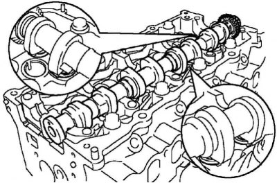
Pic. 2.374. Installation direction of cylinder caps No. 3 and No. 4
Install the intake camshaft onto the camshaft bearing housing with the cam tops of cylinders #3 and #4 pointing down as shown (pic. 2.374).
Installing the camshaft No. 2
Install camshaft #2.
Lubricate the camshaft cams and camshaft gear and camshaft bearings with engine oil.
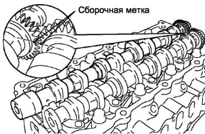
Pic. 2.375. Alignment of marks on the gears of the camshafts
Engage the gears of the exhaust and intake camshafts, aligning the marks on the gears (pic. 2.375).
Rotate the exhaust camshaft down onto the bearing housing while engaging the gears.
Install the camshaft bearing caps.
Remove old sealant (FIPG) from the bearing cover No. 5 of the camshaft.
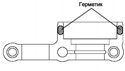
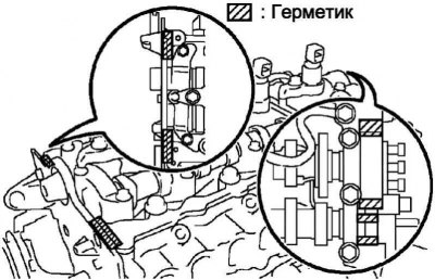
Pic. 2.376. Sealing locations
Apply sealant to the bearing cover No. 5 of the camshaft, as shown in Figure 2.376.
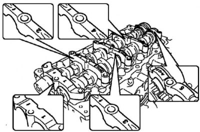
Pic. 2.377. Bearing cap installation diagram
Reinstall 5 bearing caps (pic. 2.377).
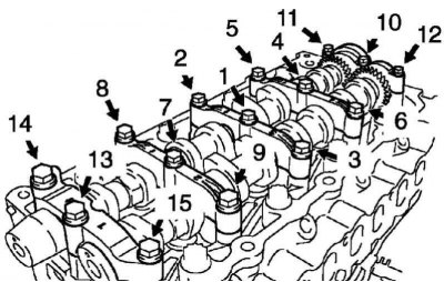
Pic. 2.378. The sequence of tightening the bearing cap bolts
In several steps, evenly, tighten the 15 bolts of the bearing caps, acting in the sequence shown in Figure 2.378.
Tightening torque: 20 Nm.
Installing the camshaft oil seal
Remove old sealant (FIPG).
Make sure that oil does not get on the mating surfaces of the stuffing box and cylinder block.
Thoroughly clean all parts from sealant residues.
Clean the mating surfaces with solvent.
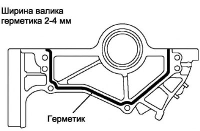
Pic. 2.379. Sealing locations
Apply sealant to the stuffing box cover, as shown in Figure 2.379.
Cut off the tip of the sealant package so that the hole diameter is 2-4 mm.
After applying the sealant, install the parts within 3 minutes and fix within 15 minutes.
Immediately remove the tip from the tube, then close the tube with a cap.
Fasten the stuffing box cover with 4 bolts. Tighten the 4 bolts evenly in several steps.
Tightening torque: 8.8 Nm.
Installation of the camshaft drive gear
Install the gear key into the camshaft groove.
Aligning the groove in the gear with the key on the shaft, install the gear on the camshaft.
Using SST, tighten the gear mounting bolt.
Tightening torque: 88 Nm.
Install the timing belt drive.
Check valve timing.
Check valve clearances.
Adjust valve clearances.
Install the camshaft position sensor.
Install the complete injectors.
Install the fuel return line assembly.
Installing the cylinder head cover
Remove old sealant (FIPG).
Pic. 2.380. Places for applying sealant to the cylinder head
Apply sealant to the cylinder head, as shown in Figure 2.380.
Install the gasket on the cylinder head cover.
Install the cylinder head cover and secure with 10 bolts.
Tightening torque: 13 Nm.
Install 4 new nozzle body seals.
Install the vacuum pump assembly.
Installing the high pressure fuel pipe No. 1
Remove the plastic bag from the injector and the vinyl tape from the common rail fuel rail.
Note. The pipes should be installed with the engine cooled to room temperature or below.
Install the high pressure fuel line.
Using SST, tighten the nut securing the high pressure fuel pipe to the common rail fuel rail.
Tightening torque: 31 Nm with SST, 34 Nm without SST.
Note. Use a torque wrench with a lever length of 30 cm.
Note. After installation, make sure that the high pressure fuel pipe is not deformed and installed correctly. If the tube is deformed or cannot be installed correctly, replace the tube with a new one.
Using SST, tighten the nut securing the high pressure fuel pipe to the injector.
Torque: Used tubing 42 Nm with SST, 46 Nm without SST.
For new tubing: 31 Nm with SST, 34 Nm without SST.
Install the 2 upper high pressure fuel line retainers and secure with 2 nuts.
Tightening torque: 5.0 Nm.
Note. The installation of fuel pipes No. 2, 3, 4 is carried out similarly to the installation of pipe No. 1.
Note. Install other components in the reverse order of removal.