
Fuel pump circuit
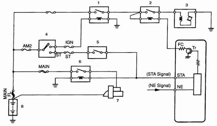
1. The main relay of the EPI fuel system; 2. Fuel pump relay (breaking the circuit); 3. Fuel pump; 4. Ignition lock; 5. Parking and neutral position switch; 6. Starter relay; 7. Starter; 8. Battery
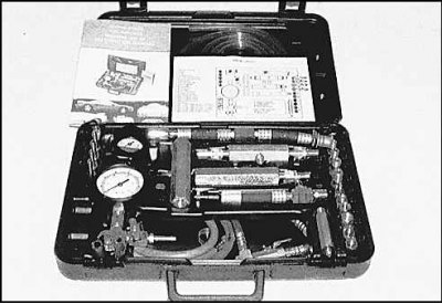
Fuel system test tool kit
General check
1. Check that there is enough fuel in the fuel tank.
2. Check if the fuel pump is working. Turn the ignition on and listen to the fuel filler neck, you should hear a short buzzing sound. If the pump does not work, check the electrical circuit of the pump.
Pressure test
1. Release the pressure in the fuel system. Disconnect the tube from the fuel filter and connect a pressure gauge to the tube and to the fuel filter using an adapter.
2. Turn the ignition key to the ON position (engine not running, air conditioning off). The fuel pump should turn on for approximately two seconds. The pressure in the system should increase and stay at the same mark. The pressure must not fall below the minimum specified in the specifications (see subsection 6.2.).
3. Start the engine and warm it up to normal temperature. Record your meter readings and compare them to specifications.
4. If the fuel pressure is out of specification:
- the pressure is too high - check the fuel pressure regulator, replace the regulator if necessary;
- pressure too low - replace fuel filter. If the pressure is still low, check if the injector or injectors are leaking. Check the condition of the fuel pump.
Checking the electrical circuit of the fuel pump
1. If the pump is not running, check the IGN and EFI fuses located in the fuse box in the engine compartment. Replace the fuses if necessary and check again if the pump is running. If the pump still does not work, check the pump electrical circuit for a short circuit.
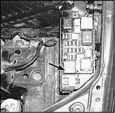 | 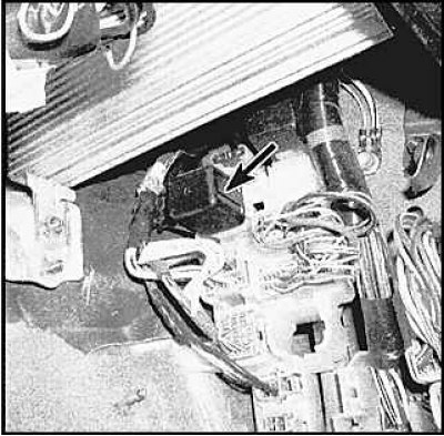 |
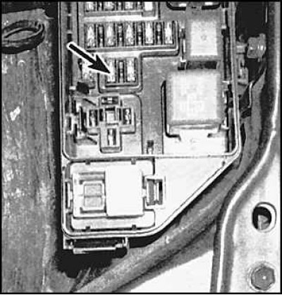
2. If the pump still does not run, remove the EFI relay and check for battery voltage at the relay socket pins. Voltage must always be applied to one of the contacts, voltage to the other of the contacts must be applied when the ignition key is turned to the ON position. If no voltage is applied to the contacts, check the wiring from the relay box to the battery. If voltage is applied to the socket contacts, check the relays themselves. The main EFI fuel system relay is located in the relay and fuse box in the engine compartment (indicated by the arrow in the figure on the left). The fuel pump relay is located in the relay and fuse box in the passenger compartment on the passenger side (indicated by the arrow in the figure on the right, Avalon models).
3. If the relays are good and the pump still does not work, check if the pump is receiving voltage. If voltage is applied, then the pump is faulty and must be replaced.
Checking the main relay of the fuel system (EFI)
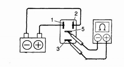
Toyota relay
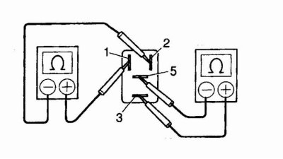
1. Ohmmeter; 2. The circuit is open; 3. Ohmmeter; 4. Circuit closed
Nippondenso relays
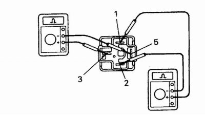
1. Ohmmeter; 2. The circuit is open; 3. Ohmmeter; 4. Circuit closed
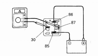
Bosch relay
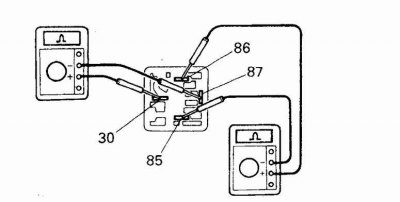
1. The circuit is closed; 2. Ohmmeter; 3. Ohmmeter; 4. Circuit open
Remove the relay and connect the tester to pins 1 and 2 (Toyota relay) or 85 and 86 (Bosch relay). The circuit between these contacts must be closed, otherwise replace the relay. Circuit between pins 3 and 5 or 30 and 87 (Bosch relay) must be open.
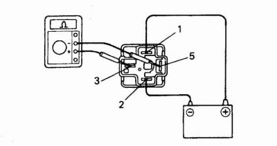
Toyota relay
1. Ohmmeter; 2. The circuit is closed; 3. Battery
When battery voltage is applied to pins 1 and 2, the circuit between pins 3 and 5 should be closed. Otherwise, replace the relay.
Nippondenso relays
1. Battery; 2. Ohmmeter
When battery voltage is applied to pins 1 and 2, the circuit between pins 3 and 5 should be closed. Otherwise, replace the relay.
Bosch relay
1. Battery; 2. Ohmmeter; 3. Circuit closed
When battery voltage is applied to terminals 85 and 86, the circuit between terminals 87 and 30 must be closed. Otherwise, replace the relay.